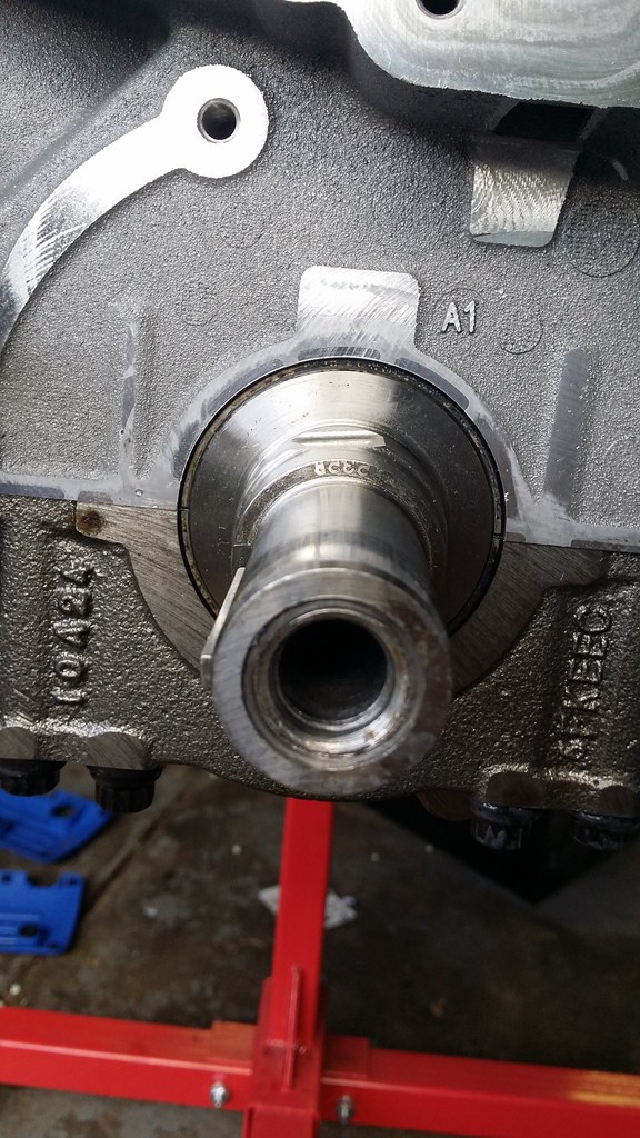
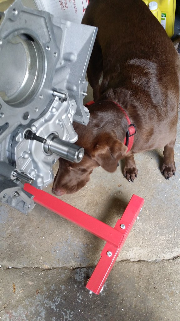
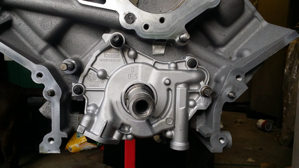
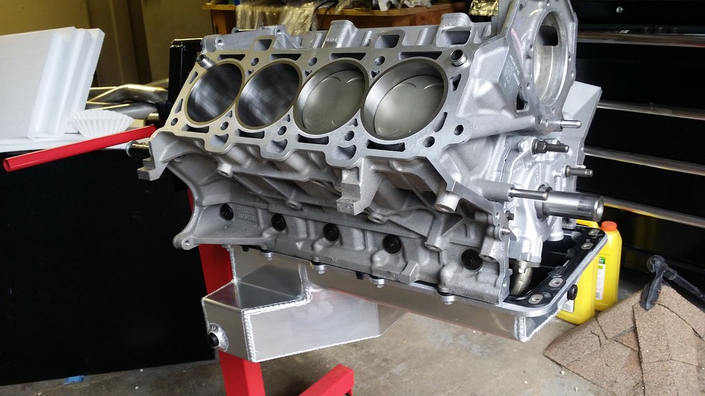
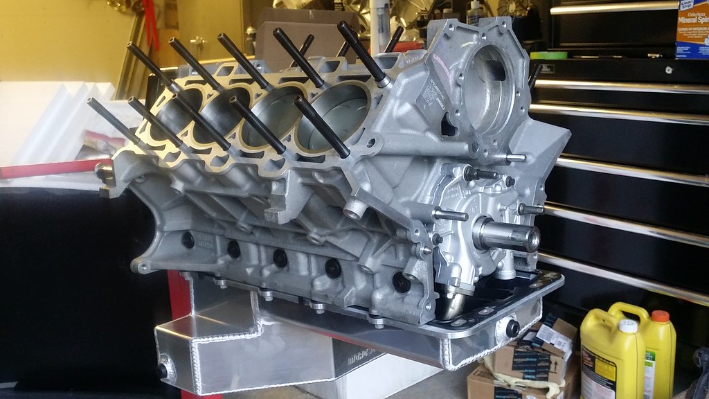
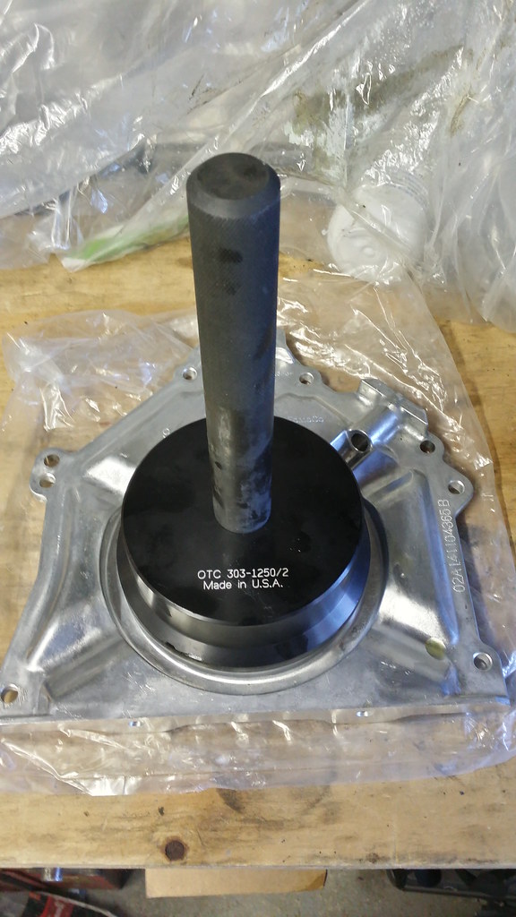
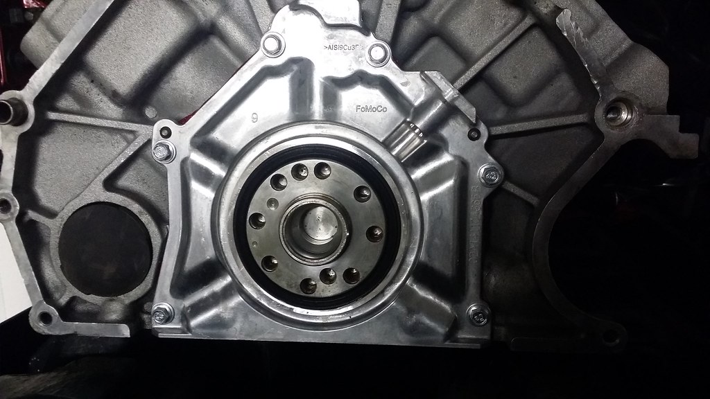
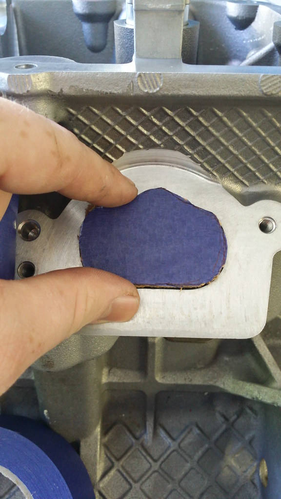
That being said, I got to work on getting the engine on the stand …. Although I jumped the gun a little :/ I wanted to go ahead and put the Rear main seal and retainer plate in before I bolted it up to the stand, but I didn’t have the rear main seal tool or the old seal, nor could I find a piece of PVC that was the same size so I can always put that on when I get the tool. As is, the shortblock isn’t that heavy so I can put it back up on the tailgate of the pickup in its crate and put it on then.
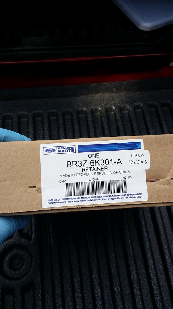
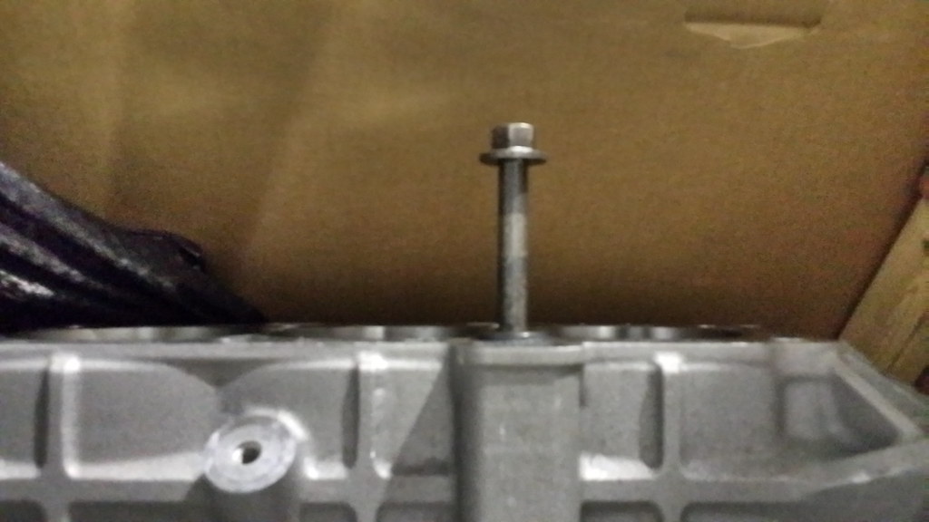
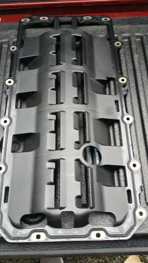
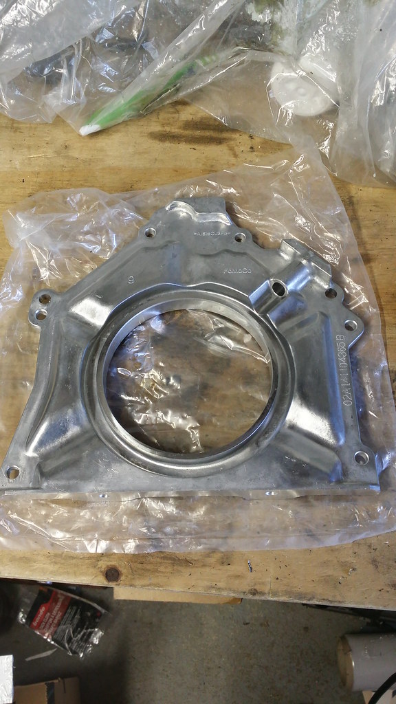
Retainer plate
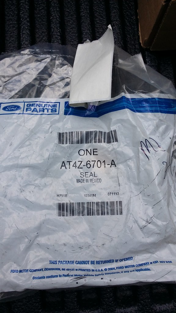
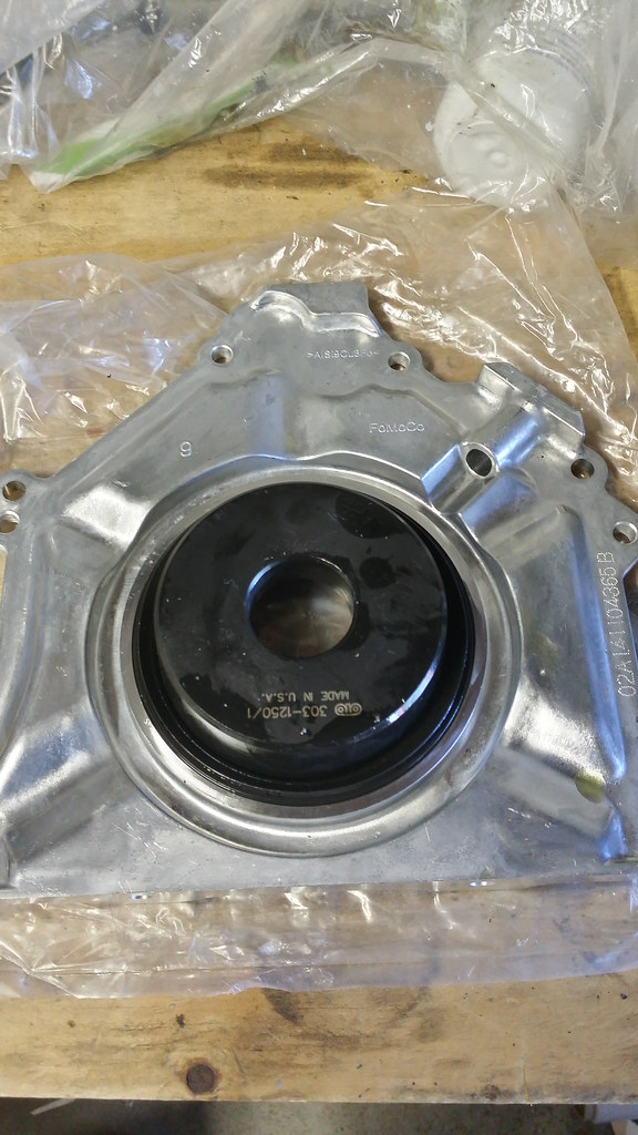
Rear Main Seal
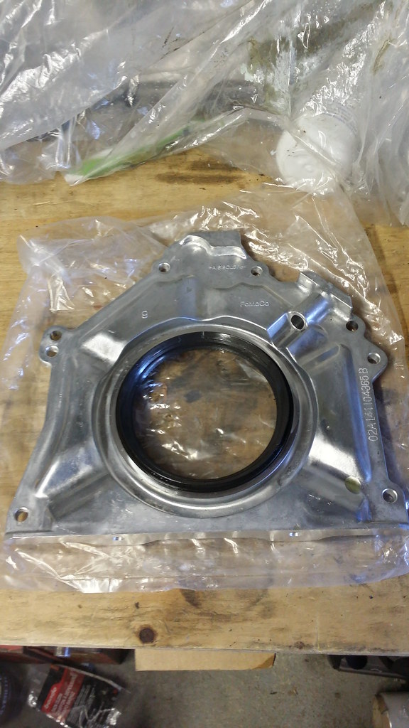
Retainer plate
Rear Main Seal
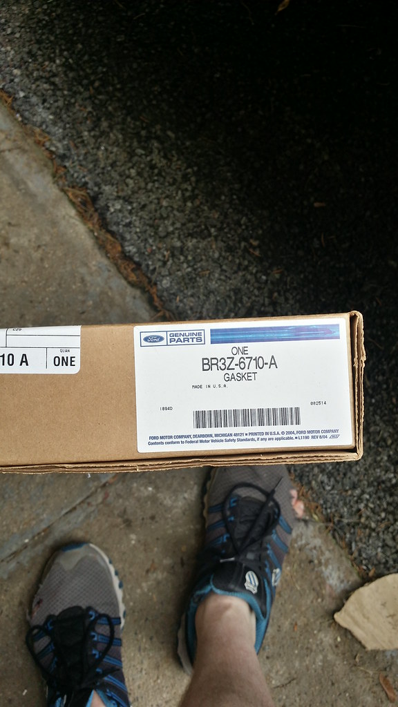
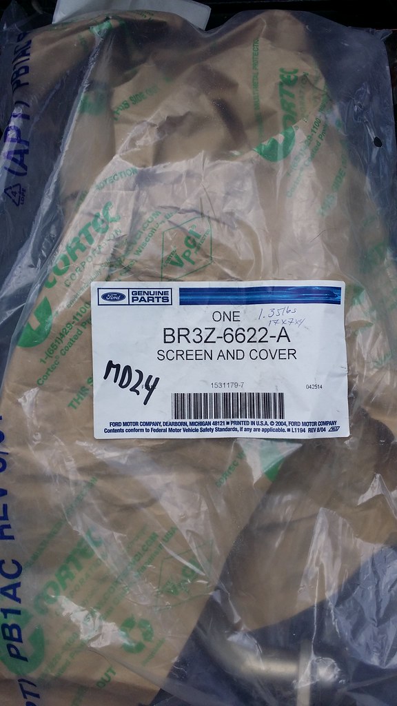
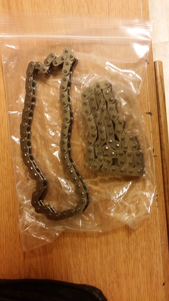
- Rear Main Seal Plate (Retainer) - BR3Z-6K301-A
- Rear Main Seal - AT4Z-6701-A