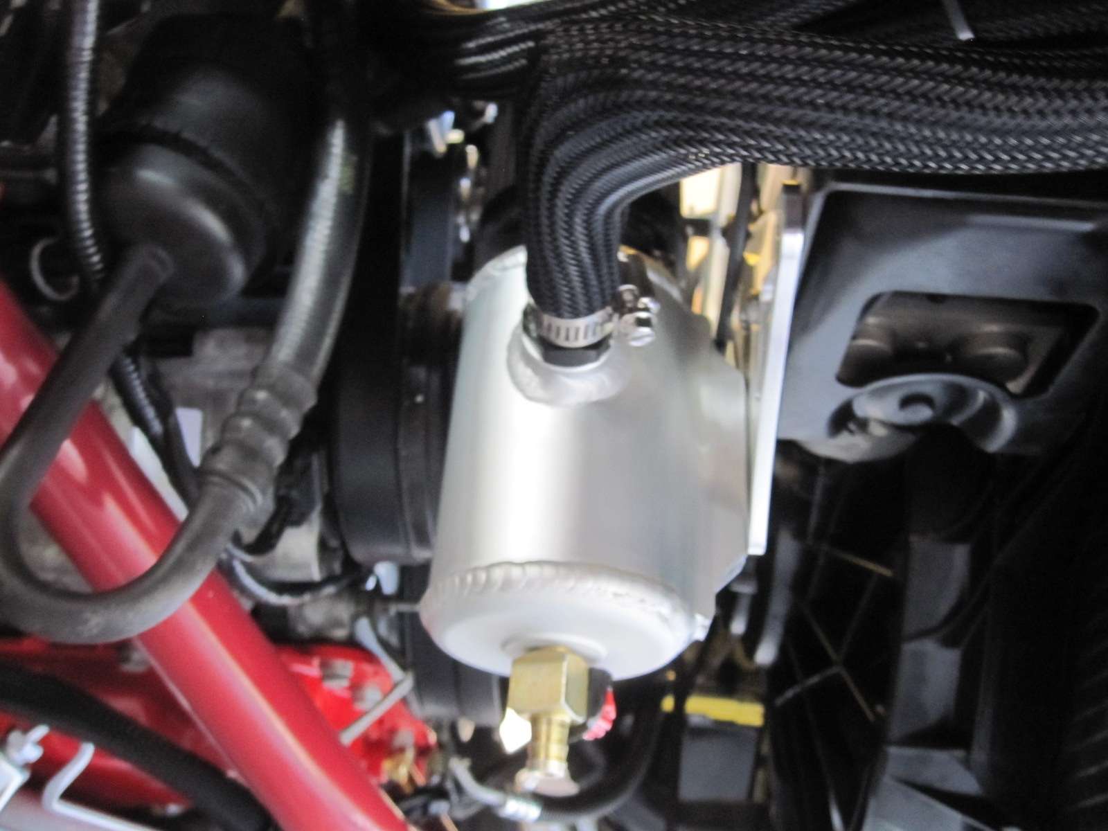
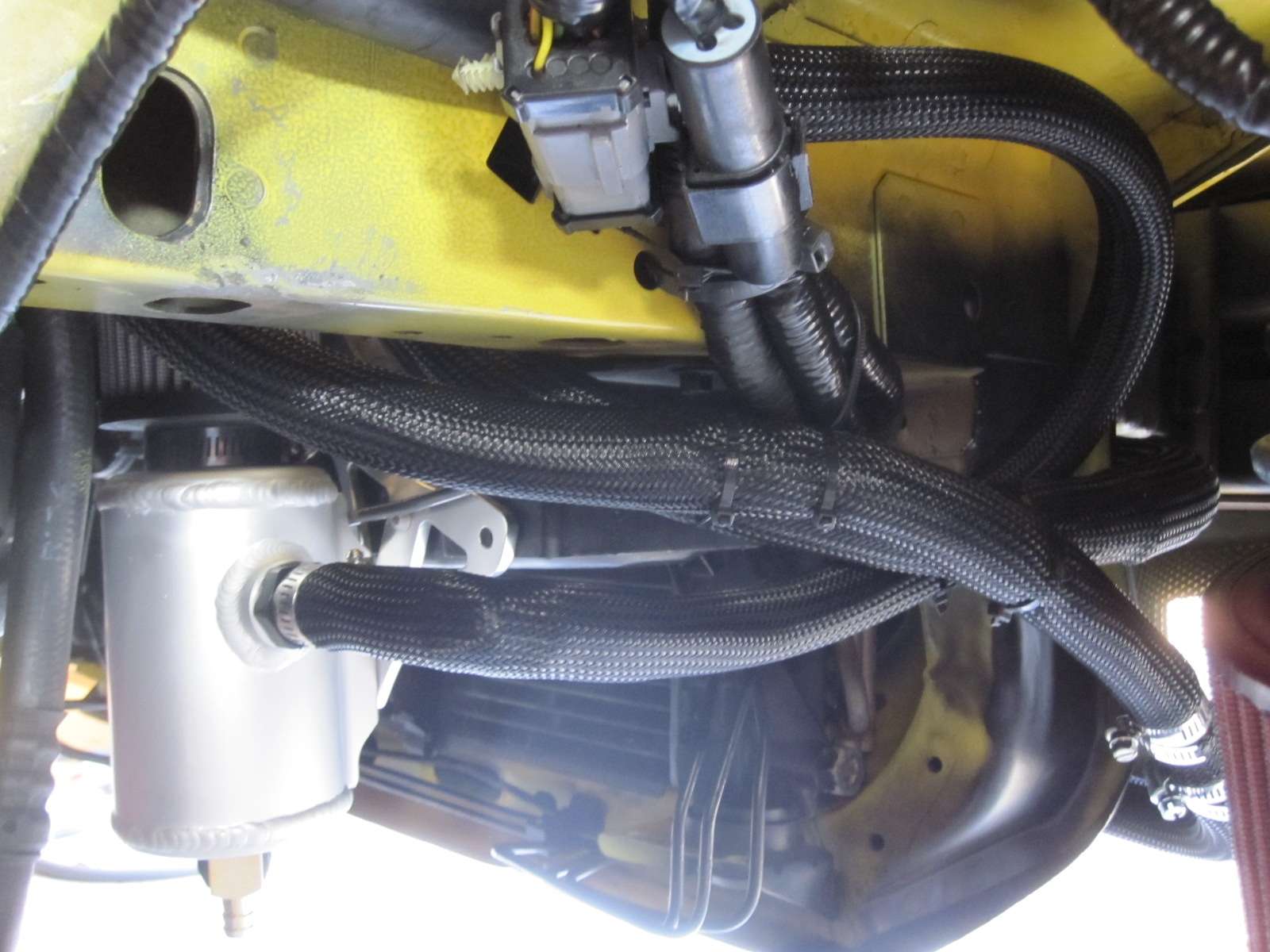
Tork Tech Terminator Install

tobynt

Active Member
Established Member
Joined
Jan 23, 2011
Messages
2,047
Location
Nashville TN
Stiegemeier (Steggy) Stage 6 Tork Tech Terminator install

I got the blower back from Stiegemeier. It has a Stage 6 port. The Throttle body and Plenum was also ported but the Plenum is a "Non-Weld" port. Below are some pictures of the blower.


img0281xt.jpg


img0285k.jpg


img0294v.jpg


I'm not running an EGR system on mine. I had ordered two different "EGR" block off plates before starting the build. I order one from Billet Depot on Ebay and another from Jegs. The Billet Depot piece is just stamped or "blanked" aluminum. I ordered this one because it was only about $8.00 the best I can recall. I tried my hand at polishing on this part. The reason I order the Jegs piece, was because it actually had an "O-ring" seat milled into it and I wasn't going to have to use any silicon. It is also a much "beefier" part.

You can see in the pictures below. I used the Billet Depot "EGR" block off to block off the cobra IAT sensor port on the blower. I had to trim two areas on it to work. The bolt hole spacing for the IAT sensor port is the same as the EGR port. If your looking for a cheap route to block off this port without having to tap it. I highly suggest doing this. It only cost me about $8.00 and I was able to practice some polishing on it. I also included pictures of the Jegs part.


img0293bu.jpg


img0289gu.jpg


Mounted the intercooler to the bottom of the blower. Not a lot can be said about this. Just don't forget to use "Loc-tite" on the bolts. First you mount the adapter plate. Then mount the intercooler to the adapter plate.


img0298ci.jpg


img0300bn.jpg


img0302xb.jpg
 
Last edited:

tobynt

Active Member
Established Member
Joined
Jan 23, 2011
Messages
2,047
Location
Nashville TN
Stiegemeier (Steggy) Stage 6 Mounted Tork Tech Terminator install

Fairly long day trying to install the new blower. It turns out I had the same problem with the bolt holes for the lower that I had with the fuel rails. When I started to torque them down. About the time I hit 15 ft lb of torque. It pulled the threads out. I had to back up and drill out the M8x1.25 threads and tap those for 3/8-16. I have no clue why I had this problem with my kit. But, it is what it is kind of thing. I didn't have to drill out and tap two of the holes. Those would be the ones that only thread in to the adapter plate. So, you may notice in the pictures below. The cap screw heads are a lot larger then the ones on most kits.

I had to remove the top pulley from the bridge when I inserted the intercooler ports. This allowed enough clearance for me to do the install in parts instead of dropping the blower mounted to the lower at one time. Useful tip for sliding the ports in through the intake to the intercooler. Use some liquid PTFE on the O-rings. You don't have to use a lot. Just enough to coat them so they will slide easily through the holes. This will help prevent them from getting necked or damaged while doing the install.

Still a few more things left to finish the instal but here it is. Hopefully I don't have to remove anything and this is the last time I will have to install the blower.

img0323ni.jpg


img0325jl.jpg


img0326z.jpg
 
Last edited:

tobynt

Active Member
Established Member
Joined
Jan 23, 2011
Messages
2,047
Location
Nashville TN
I didn't take a picture of it.

Depending on what type of bracket you get will determine how you make yours. Take off the plastic radiator shroud. You will see that you already have two holes with nuts welded on the back side.

It pretty much a test and fit kind of deal. My bracket has a total of four holes in it. Two that mount to the cooler tank and two that mount to the radiator support brace. After that I had to trim the excess length off of the bracket, so it wouldn't hit the radiator.
 

tobynt

Active Member
Established Member
Joined
Jan 23, 2011
Messages
2,047
Location
Nashville TN
Before and After Tork Tech Terminator install

I got the JLT pipe and filter on. I was going to get a polished stainless one piece pipe made for it. When I first started talking about the part. It was going to cost around $250.00 but after I got the final quote. It came in at $375.00

I was prepared to pay $250.00 for a pipe that I wanted but definitely not $375.00. So, I'm using the painted plastic PVC pipe for now. Maybe in the future I will be able to track down someone that will make that part cheaper but until then...I'm running this one.

I also got to looking through some of the before pictures. A bit of reminiscing if you will. Even though I still have to route the intercooler lines and main coolant lines...It has diffidently came a long way from where I begin.

Here are the before and afters to this point.

img9585hs.jpg


img0340kt.jpg


img0351yg.jpg


img0336l.jpg
 
Last edited:

D2Fresh16

Active Member
Established Member
Joined
Jan 17, 2007
Messages
1,683
Location
New York
Looks great, man! I installed this on my '04 PI Swapped '97 GT last winter. What a nightmare; between the fuel system and random issues all along the way that Tork Tech has no information on. Regardless, I'm very happy I did it, the car is an absolute blast to drive. Best of luck on finishing it. The end product is well worth all the effort
 

tobynt

Active Member
Established Member
Joined
Jan 23, 2011
Messages
2,047
Location
Nashville TN
Well, I finished the coolant tube design. Sent it out for quotes and got 8 no quotes back. Back to the drawing board. Diffidently looks like I'm going to have to get this custom made with elbows and welding instead of 3 parts of bent tubing welded together.

Either way, here is the original design for entertainment. Its also one of the first versions...This design was going to be half molded hose and half hard tubing. The final part will be all tubing.


tubeg.jpg
 

tobynt

Active Member
Established Member
Joined
Jan 23, 2011
Messages
2,047
Location
Nashville TN
Some people on Ebay absolutely kill me. I have been selling off parts from my car that I no longer need.

Why do people bid up and never pay. They seem very diligent with making sure they bid on the item, then you can't get a response after the auction is over. Waste of time and money....just pisses me off. I would rather get an email saying "yea, sorry bud...I decided to screw you and not pay". At least with that I can go ahead and turn it in as a non-payment instead of having to wait almost two weeks to get a partial insertion refund from ebay and re-list it.

Just had to rant...............
 

cuda99

Cuda99
Established Member
Joined
Apr 5, 2008
Messages
79
Location
Louisville, KY
Coolant Tube Design

I will have to say that I am very interested in your tube design and have been trying for some time to get a different system fabricated up. I never liked the way the Tork Tech kit was set up. In its defense it is functional and probably cuts down on costs, however, it has its flaws. If you do end up making it I would certainly be willing to help offset some of your cost if you were to make two.

The one thing that wasn't clear by your design is where the thermostat would go. Either way keep on trucking brother, your car looks great!
 

tobynt

Active Member
Established Member
Joined
Jan 23, 2011
Messages
2,047
Location
Nashville TN
Thermostat will be going in-line. I already purchased it and the 170 stat to go inside of it. Still waiting on quotes for the latest design. Its a lot simpler but still the same concept. Tight and routed between the bridge and intake while going under the snout.

Here is the stat housing I got. I ordered the 1 1/2".
Meziere Inline Thermostat Housings - JEGS
 
Last edited:

tobynt

Active Member
Established Member
Joined
Jan 23, 2011
Messages
2,047
Location
Nashville TN
Tork Tech Terminator Install Intercooler system routing

I got the Intercooler System routed and test for leaks over the weekend. Good News, no leaks. On a side note....the "side" port on the Saleen tank does not come drilled out. This is where I wanted to put my return port. After about an hour of not knowing why it wasn't circulating, I finally figured it out and drilled the hole out. Now, all is well

I posted a graph to show how I routed mine. Its a very rough graph. The series is as follows.

Starting with the Tank.
Lower Tank port to inlet of pump
Outlet of Pump to top port of heat exchanger
Lower port of heat exchanger to lower port of intercooler (lower intake)
Top port of intercooler to top port of tank (return line)


My Afco heat exchanger came with two hoses. One of those hoses had some tight bends in it. I wound up cutting it in half and used it in two different places. I also purchased a 3/4 "L" hose. And 10 feet of 3/4 hose. Two hose connectors and one "unicoil". In total I used about 16 feet of hose. I would describe verbatim how I routed it but everyone will be different and its all "test and fit". I did take pictures though, so it should give you an idea of where I put the hoses.


Routing Diagram
routing.jpg


Intake Intercooler
engineintercooler.jpg


Saleen Tank
tankx.jpg


Bending around to travel from heat exchanger and pump to intake and tank.
toheatexchanger.jpg


Heat exchanger
hearexchanger.jpg


Pump (note: my pump is mounted on the drivers side.)
pumpb.jpg
 
Last edited:

tobynt

Active Member
Established Member
Joined
Jan 23, 2011
Messages
2,047
Location
Nashville TN
Catch Can....Vented valve covers tork tech terminator install

I finally got my valve covers vented to a "Catch Can"...or more appropriately called an "Oil Breather Tank". Catch Can is more along the way of a none vented system that would be found in-line with a PCV valve to separate the oil before being routed back in with the air induction system. Also more appropriately called an "Oil Separation System". An "Oil Breather Tank" is vented to the atmosphere. Since it has become common for everyone to refer to both systems as a "Catch Can"….. I decided to toss that "Key Word" in with this post.

The parts I used are as follows.

1. #555-52202 - JEGS Oil Breather Tanks
JEGS Performance Products 52202 JEGS Oil Breather Tanks

2. #555-51133 JEGS "Just-A-Ble" Mounting Bracket.
JEGS Performance Products 51133 JEGS Billet Universal Automatic Transmission Catch Can

3. #555-110596 JEGS Hose Barb Fitting
JEGS Performance Products 110596 JEGS Oil Breather Tanks

4. 15 feet of 5/8" Gates heater hose from O'Reilly Auto Store. (I only used approximately 13 feet.)

5. I used two 5/8" 90 degree heater hose barbs & one 5/8" heater hose "Tee" fitting.

I used the Jegs "Just-A-Ble" (yes, for some reason its called "Just-A-BLE". not to be confused with "Just-A-Bite". Apparently it’s actually called "Just-Able" but some jack ass put a hyphen in the name for marketing. It makes no sense to me.).......anyway, back to the install. I mounted the bracket to my ABS bracket. I then mounted the Oil Breather Tank to the bracket. I used the plug that came with the tank and blocked off the port pointing to the driver’s side. I then used the -10 AN (5/8" hose equivalent in "-AN" fittings) hose bard fitting I purchased separately and installed it pointing toward the passenger side.

Driver’s side valve cover hose is pointing toward the "bulk head" and has the 90 degree heater hose barb inserted pointing toward the passenger side. Routed hose from that barb to the 5/8" heater hose "Tee" where it would mate up with the passenger side hose. I then ran the hose into the passenger side fender well. Inside the fender I routed the hose up along the top of the fender. Then down to the Oil breather tank. I basically made an "anti-siphon" loop with it inside the fender well. In the long run this may not matter but, it might possible help insure the tank doesn't feel up with every drop of oil that gets pushed up into the hose.

Below are the pictures of the tank installed along with some pictures of how I routed the hose.


topshv.jpg


sideviewb.jpg


undercar.jpg


hosedriverside1.jpg


hosedriverside2.jpg


hosepassangerside.jpg


routing1.jpg


routing3.jpg


routing2.jpg


routing4.jpg


routing5.jpg
 
Last edited:

D2Fresh16

Active Member
Established Member
Joined
Jan 17, 2007
Messages
1,683
Location
New York
Looking good! What did you do for a upper radiator hose? I hate how mine is bent, I've been wanting to change that but still haven't gotten around to it.
 

tobynt

Active Member
Established Member
Joined
Jan 23, 2011
Messages
2,047
Location
Nashville TN
Looking good! What did you do for a upper radiator hose? I hate how mine is bent, I've been wanting to change that but still haven't gotten around to it.

Still working on it. Should have something worth posting next weekend. Well, let me rephrase that. I will have something with an update and my approach to resolve next weekend.

I will be wiring up my gauges tomorrow and then the coolant hose is the only thing I have left to take care of. So, its going to get my full attention after the gauges are finished.

Today I'm changing the oil and dropping the car down from the jack stands. It's been off the ground since Mid November. Kind of an exciting day.
 

D2Fresh16

Active Member
Established Member
Joined
Jan 17, 2007
Messages
1,683
Location
New York
Still working on it. Should have something worth posting next weekend. Well, let me rephrase that. I will have something with an update and my approach to resolve next weekend.

I will be wiring up my gauges tomorrow and then the coolant hose is the only thing I have left to take care of. So, its going to get my full attention after the gauges are finished.

Today I'm changing the oil and dropping the car down from the jack stands. It's been off the ground since Mid November. Kind of an exciting day.

Nice! Wiring my gauges drove me insane.
 

tobynt

Active Member
Established Member
Joined
Jan 23, 2011
Messages
2,047
Location
Nashville TN
Gauge Install Tork Tech Terminator install

I got my gauges wired up and installed. Pretty uneventful. Just followed the directions. I went with Autometer Ultra Lite II Series (The newer ones with LED lighting). I have the three most essential gauges for a blower. Fuel Pressure, Wideband Air/Fuel..and of course VAC/Boost gauge. The pictures showing them with the lights on...have a red hue to them. This was from the Camera and not how the gauges look with the lights on. The pictures do not do them justice.

Here they are.


gauge1s.jpg


gauge2q.jpg


gauge3.jpg


gauge4.jpg
 
Last edited:

tobynt

Active Member
Established Member
Joined
Jan 23, 2011
Messages
2,047
Location
Nashville TN
Traveling this week.........So, in regards to the coolant crossover pipe. This is all you get until next Sunday.


To be continued.........................


teaserc.jpg
 

Users who are viewing this thread


Top