Tork Tech Terminator Install

tobynt

Active Member
Established Member
Joined
Jan 23, 2011
Messages
2,047
Location
Nashville TN
Decided to move my thread over to this forum. Might take a few days to get it all moved over and up to date. But, I like this forum better so...here I am!

Here is a link for the Tork Tech Terminator kit.

Terminator GT Kits for the '99-04 GT - Tork Tech

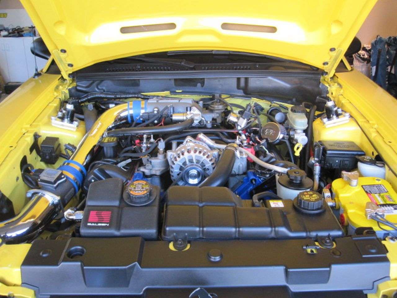
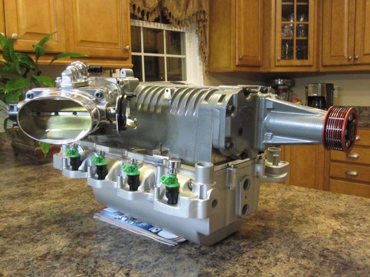
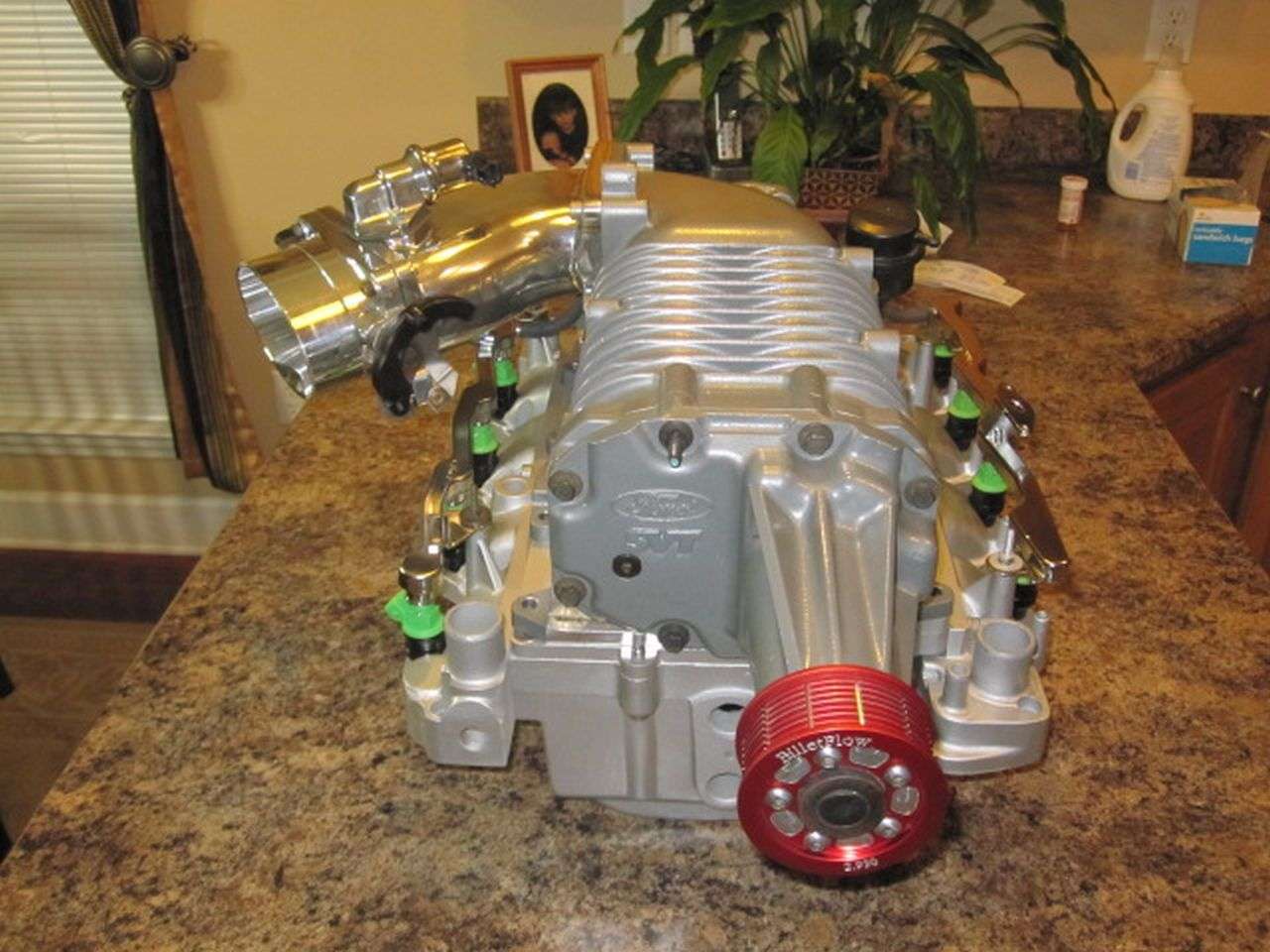
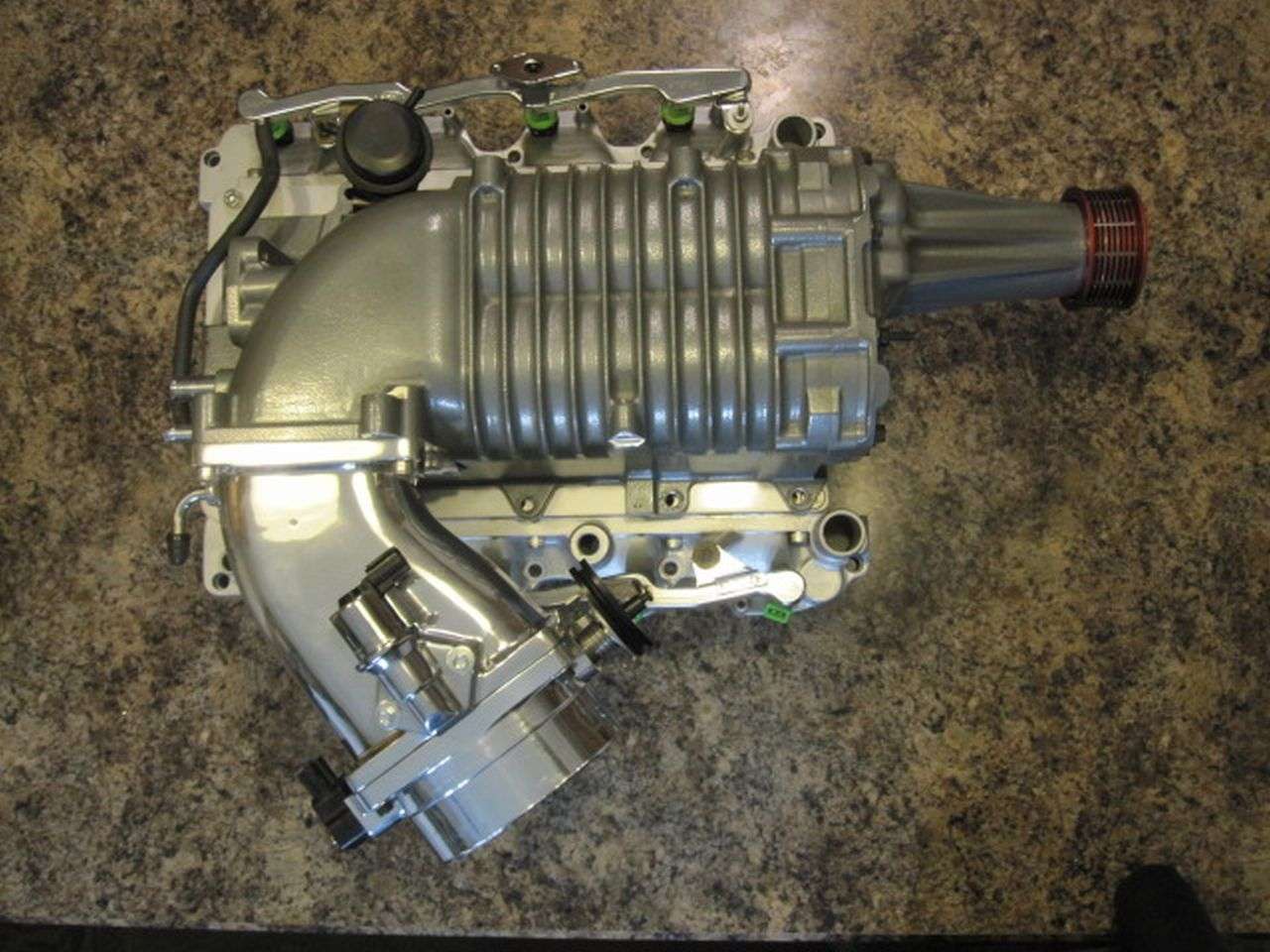
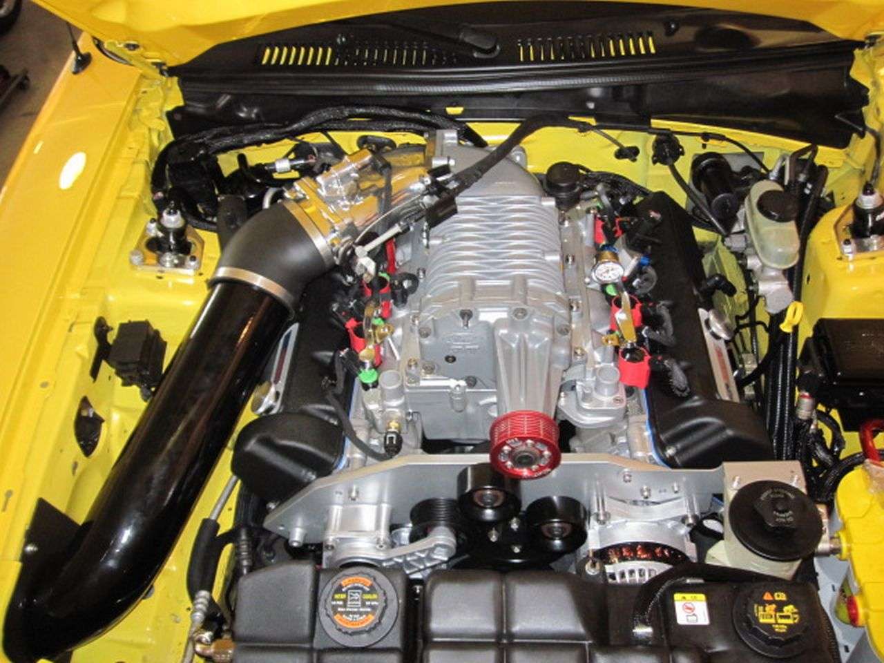
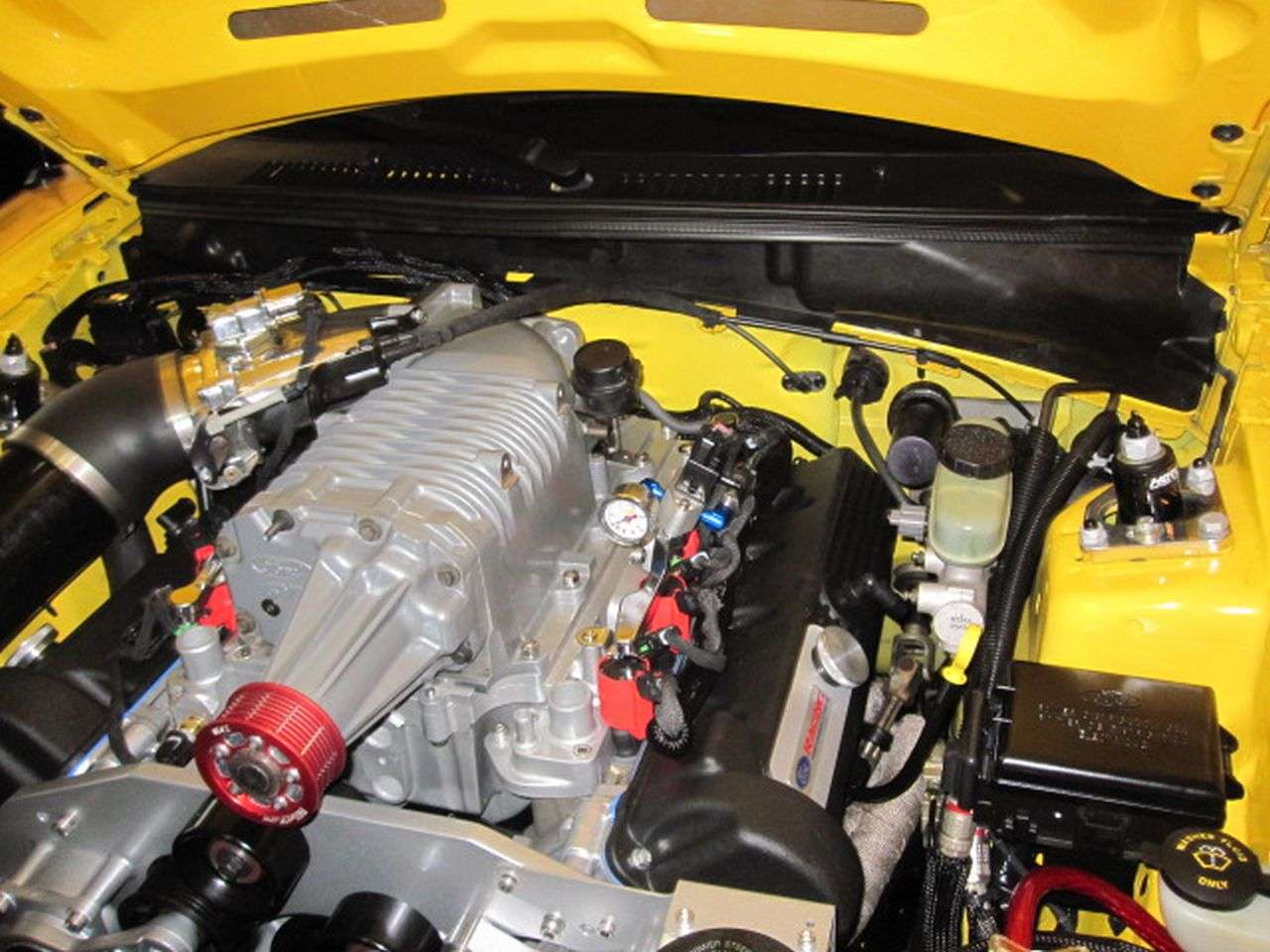
This kit, as outlined on the website. Only consist of the necessary components to get the Factory 2003-2004 Terminator Cobra Eaton M112 to bolt up to our PI 4.6 two valve Engines and drive it with a pulley system. The company does offer up other items to help complete the conversion but those components are not included in the kit.

Typical cost at this time will run you in the $1,850-$2,100 depending on which kit you get. The non-intercooled kit cost less and the intercooled kit cost more. My kit cost was a little over $2,100 and that included the shipping charge.

The website has a "parts list" and an estimated cost of said "needed" parts. Below is my parts list and what it cost me. My cost is substantially more but I also opted to purchase new parts and not used. I also opted the get a few things that would be considered an "up-grade" from the bare minimum of what is really needed. So, at this point my cost has become substantially more then what someone would be able to perform a budget build for.

Only the Tork Tech kit price includes shipping. None of the other prices include what I may have paid for shipping. I have also not included the fuel pumps, fuel tank, programmer in the "Kit List" or the Total Investment listed.

For those who are interested, Here is what I did not include in the "Tork Tech Parts List". This is what I have had for some time now already installed on the car. All parts are New except for the Dual pump assembly and the Eaton M112 as I have noted below.


Part Number--------------Manufacture ---------------------------Price Paid

M-9407-C46 -------------Cobra Dual Fuel Pumps (USED)------------$250.00
M-9002-C46A-------------Ford Racing Cobra Tank:-----------------$299.99
9600 --------------------SCT Livewire:----------------------------$509.00
4332 --------------------SCT Pro Racer:---------------------------$299.00


Parts with Part Numbers and price paid so fair. This is about a 14 month collection of parts so far.

Part Number------------Manufacture-------------------------------Price Paid

178-630----------------Saleen Intercoolor Expansion Tank------------$99.99
2R3Z-6F066-AA---------Stock Eaton M112 (USED)-------------------$550.00
Terminator Kit-----------Tork Tech Tork---------------------------$2,165.00
9C1Z-12A697-B---------Lightning threaded IAT sensor-----------------$18.99
2R3Z-9A758-AA---------Ford 03-04 cobra throttle cable---------------$48.99
2R3Z-9A825-AA---------Ford 03-04 cobra cruisecontrol cable----------$30.99
2R3Z-9728-BA-----------Ford 03-04 cable bracket---------------------$30.99
M-12579-L54------------Ford Racing 90mm Mass air meter-------------$79.99
280150558--------------Bosch 42 lbs flow matched injectors----------$299.00
JLTCAI-FMC-0304-------JLT true cold air CAI-------------------------$197.95
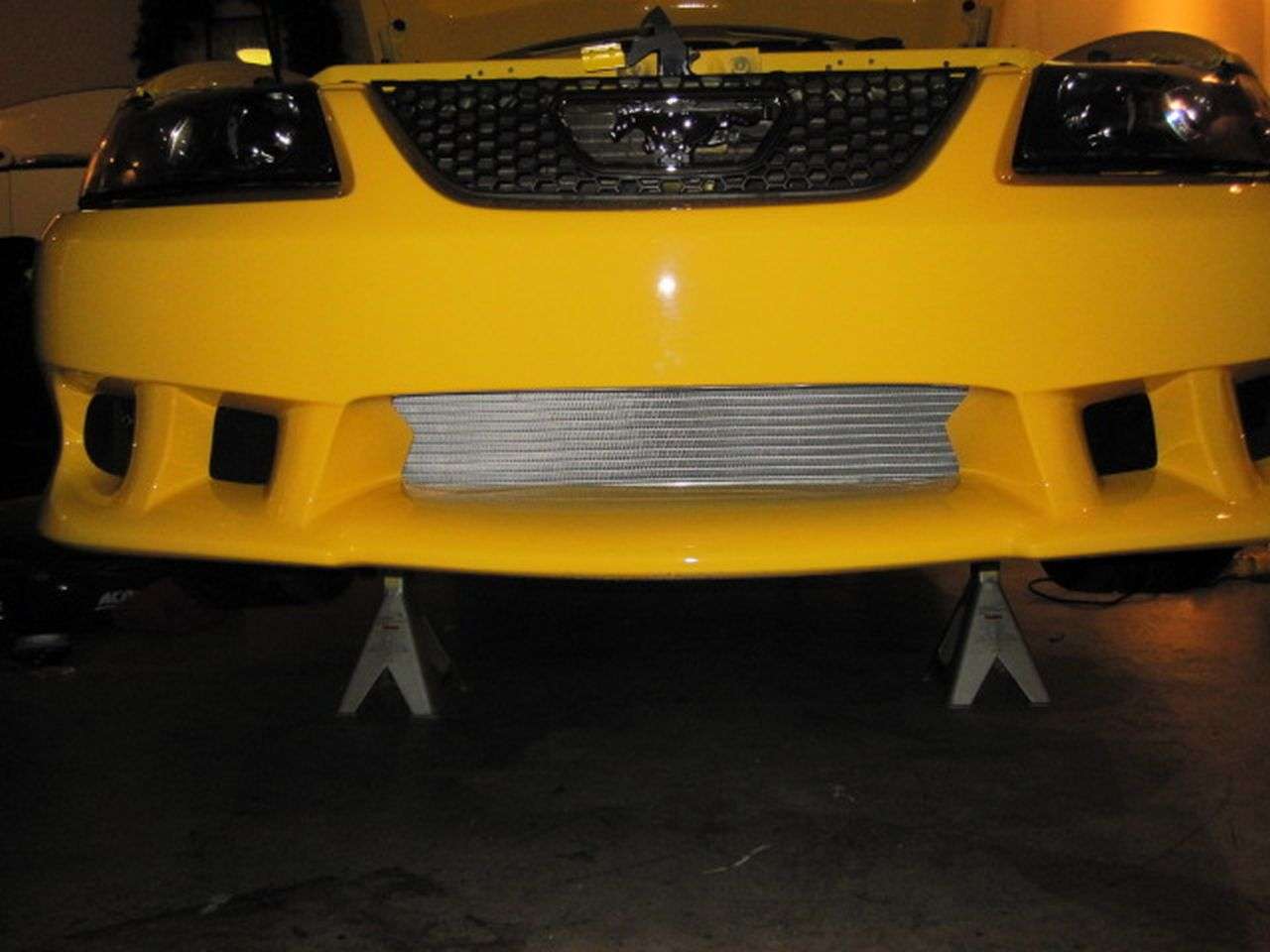
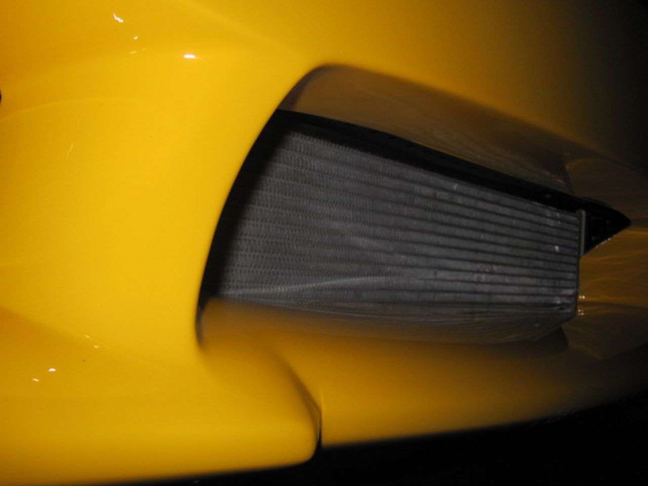
80275NDP--------------AFCO Dual Pass Heat Exchanger---------------$309.95
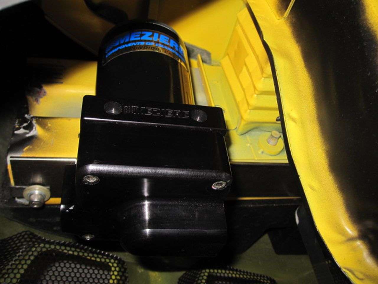
MEZ-WP136S----------Meziere Intercooler pump----------------------$195.95
MEZ-WP12034B--------Meziere Intercooler Pump Fittings---------------$39.90
M-9926-SC46----------Ford Throttlebody and elbow-------------------$150.00
F4SF-9B989-AA--------Throttle Position Sensor-------------------------$0.00 *Included New with TB
2R3V-9F715-AA--------Idle Air Control Valve----------------------------$0.00 *Included New with TB
BD-5009-4.6-----------Billet Depot EGR DELETE PLATE------------------$7.99


Total: $4,025.68


Including the the parts I already had (fuel pumps, fuel tank, programmer stuff) My total investment so far to get blown is $5,383.57
__________________
 
Last edited:

tobynt

Active Member
Established Member
Joined
Jan 23, 2011
Messages
2,047
Location
Nashville TN
Tork Tech Terminator Install Intercooler syatem

Intercooler system installed and mounted. I haven't plumbed anything yet. Figured it would be best to wait until the full system is installed.

Afco Dual pass heat exchanger was pretty easy to install. The intercooler pump is a Meziere remote mount pump. The plastic intercooler tank was simple to mount but cost me more than I thought to purchase the fittings for the tank.

Mounting hardware for the heat exchanger: 72" long piece of mild steel flat stock from the hardware. two 5/16th one inch long bolts. 2 flat washers and 2 lock washers for the bolts. 1 tube of Loctit epoxy for metal and two 1/4" locking nuts.

The heat exchanger has two locator post sticking up out of the top. I used a tapping die to thread these. Drilled two holes in my long flat stock of steal. mounted the heat exchanger to it then mounted my flat stock steal to the front bumper support.

two pieces of angle aluminum stock was used to mount the pump and the intercooler tank. Not a lot of detail can be said about it. One of those test fit it and modify as needed.


Meziere Intercooler pump
intercoolerpumptorktech.jpg
http://profile.imageshack.us/user/tobynt


AFCO Dual Pass Heat Exchanger
img9504l.jpg
http://profile.imageshack.us/user/tobynt


AFCO Dual Pass Heat Exchanger
img9508bi.jpg
http://profile.imageshack.us/user/tobynt


AFCO Dual Pass Heat Exchanger
afcoheatexchangertorkte.jpg
http://profile.imageshack.us/user/tobynt


Saleen Intercoolor Expansion Tank
intercoolerreservoirtor.jpg
http://profile.imageshack.us/user/tobynt
 
Last edited:

tobynt

Active Member
Established Member
Joined
Jan 23, 2011
Messages
2,047
Location
Nashville TN
Tork Tech Terminator Install Mock Up

You will soon find out. If you have underdrive pulleys on your car. You have to ditch those and put stock back on it.

During the process of unbolting the underdrives and re-painting my timing cover silver instead of blue. I did a mock up of the blower for giggles.


Tork Tech Terminator Install Eaton M112 Mock up
torktecheatonm112mockup.jpg
http://profile.imageshack.us/user/tobynt


Tork Tech Terminator Install Eaton M112 Mock up
torktecheatonm112mockup.jpg

http://profile.imageshack.us/user/tobynt


Tork Tech Terminator Install Eaton M112 Mock up
torktecheatonm112mockup.jpg
http://profile.imageshack.us/user/tobynt


Tork Tech Terminator Install Eaton M112 Mock up
torktecheatonm112mockup.jpg
http://profile.imageshack.us/user/tobynt


Tork Tech Terminator Install Eaton M112 Mock up
torktecheatonm112mockup.jpg
http://profile.imageshack.us/user/tobynt


Tork Tech Terminator Install Eaton M112 Mock up
torktecheatonm112mockup.jpg
http://profile.imageshack.us/user/tobynt


Tork Tech Terminator Install Eaton M112 Mock up
torktecheatonm112mockup.jpg
http://profile.imageshack.us/user/tobynt
 
Last edited:

tobynt

Active Member
Established Member
Joined
Jan 23, 2011
Messages
2,047
Location
Nashville TN
Tork Tech Terminator Install Lower Block Clearance

Now that I am done playing around with taking pictures of what it will look like for no good reason. I went ahead and cleared the block for the lower intercooler line.

Doesn't take a rocket scientist to figure out whats going on here. The only exception is, the instructions call for a slot 3/4" wide by 3/8" deep. This really doesn't help other then they needed to put something in the instructions to the degree of "hey, notch the block."

With that being said, the way I did it in order to make sure I didn't waste time clearing areas that didn't need it and focused on what did, is as follows.

Basically, I set the lower intake on the heads. I then took a deep well socket and laid in the port where the coolant fitting goes. I used this as both a gauge while grinding and to mark up lines where I needed to clear, along with how deep. Picture below should give you an idea.


Tork Tech Terminator Install Block clearance
torktechterminatorinsta.jpg
http://profile.imageshack.us/user/tobynt

Tork Tech Terminator Install Block clearance
torktechterminatorinsta.jpg
http://profile.imageshack.us/user/tobynt


I also took the rubber "O-Rings" off of the intercooler fitting pipe. This allowed me to easily put it in and out of the lower intake without fighting pushing it in and out....also helps insure you don't "nick" the o-rings and damage them before the "true install". Few things to note; If you clear the block using the deep well socket as an in process gauge. The intercooler fitting pipe has a "shoulder" on it. The lower intake has a counter bore in it where the coolant line fitting goes. This acts kind of like a stop for the fitting. So, You will have to clear the block down further to make sure you have clearance for the fitting. If you just grind the block down far enough to clear the socket....you will not have enough clearance for the fitting to work.


Tork Tech Terminator Install Block clearance
torktechterminatorinsta.jpg
http://profile.imageshack.us/user/tobynt


Tork Tech Terminator Install Block clearance
torktechterminatorinsta.jpg
http://profile.imageshack.us/user/tobynt


Tork Tech Terminator Install Block clearance
torktechterminatorinsta.jpg
http://profile.imageshack.us/user/tobynt


Tork Tech Terminator Install Block clearance
torktechterminatorinsta.jpg
http://profile.imageshack.us/user/tobynt


Also, Here are some pictures of the block notched out. I couldn't find a really good picture of this before I did it and most of the pictures floating around only have close ups of the block cleared from the back side. Which in my opinion is kind of useless, considering most people will be looking at it from the front.

So the next pictures are for the folks that might stumble across this thread that actually try this install. Here you go, these pictures are for you. Maybe you will have a better idea visually of just how far down you have to clear this thing.


Tork Tech Terminator Install Block clearance
torktechterminatorinsta.jpg
http://profile.imageshack.us/user/tobynt


Tork Tech Terminator Install Block clearance
torktechterminatorinstad.jpg
http://profile.imageshack.us/user/tobynt


Tork Tech Terminator Install Block clearance
torktechterminatorinsta.jpg
http://profile.imageshack.us/user/tobynt


I used a run of the mill Dremel tool for it with the sanding rolls. Took about 30 minutes.
 
Last edited:

tobynt

Active Member
Established Member
Joined
Jan 23, 2011
Messages
2,047
Location
Nashville TN
Trick Flow Valve Covers 4.6 mustang two valve Tork Tech Terminator install

Finally cleaned up the heads intake mounting surface. Below is a picture showing the left side clean and the right not cleaned. Then a picture of both sides cleaned up. Also took a quick shot of one of the ports....just bored at that point.

Tork Tech Terminator Install Clean Intake mounting flange on one Head and not the other http://imageshack.us


Tork Tech Terminator Install Clean Intake mounting flange on Heads http://imageshack.us


Tork Tech Terminator Install Clean Intake Runner http://imageshack.us


Here's a quick picture after I painted the engine block valley.


Tork Tech Install engine block valley http://imageshack.us


Also decided on TrickFlow black valve covers. I was going to get the bare casting and have those powder coated blue but changed my mind at the last minute and pulled the trigger on the black. After putting on a Ford Racing badge to cover up the "TrickFLow" script. I'm glad I went with black. It really highlights the ford badge.


Here a some pictures of the stock valve covers compared to the trickflow.


Side by Side compare of stock and Trick Flow Valve Covers 4.6 2 valve
torktechinstallstockval.jpg
http://profile.imageshack.us/user/tobynt


Forward shot compare of stock and Trick Flow Valve Covers 4.6 2 valve http://imageshack.us


Underside of Stock Valve Covers 4.6 2 valve http://imageshack.us


Underside of Trick Flow Valve Covers 4.6 2 valve http://imageshack.us


Here they are with the badge and mounted.


Tork Tech Install Trick Flow Valve Covers 4.6 2 valve http://imageshack.us


Tork Tech Install Trick Flow Valve Covers 4.6 2 valve http://imageshack.us


Tork Tech Install Trick Flow Valve Covers 4.6 2 valve http://imageshack.us


Tork Tech Install Trick Flow Valve Covers 4.6 2 valve http://imageshack.us


Tork Tech Install Trick Flow Valve Covers 4.6 2 valve http://imageshack.us


Tork Tech Install Trick Flow Valve Covers 4.6 2 valve http://imageshack.us


Tork Tech Install Trick Flow Valve Covers 4.6 2 valve http://imageshack.us


Tork Tech Install Trick Flow Valve Covers 4.6 2 valve http://imageshack.us


Tork Tech Install Trick Flow Valve Covers 4.6 2 valve http://imageshack.us
 
Last edited:

tobynt

Active Member
Established Member
Joined
Jan 23, 2011
Messages
2,047
Location
Nashville TN
Tork Tech Instructions call for you to modify one of the studded bolts on the timing chain cover that is above the power steering pulley. It also says to remove the Battery cable bracket that attaches to the bolt it says to cut off.

I have had a few questions about where to get the bolt I used for the timing cover.
Here is a direct link to the Button Head cap screws M8x1.25 60mm long Stainless I used
Link------------> http://www.grainger.com/Grainger/so...catalog/N-8n7Z1z0o0foZ1z0nyv6Z1z0jct7Z1z0nzs9


Here are the pictures from the Tork Tech install guide for reference and what they recommend doing.


Tork Tech Stock Picture Power steering bolt 1
torktechstockpicturepow.jpg
http://profile.imageshack.us/user/tobynt


Tork Tech Stock Picture Power steering bolt 2
torktechstockpicturepow.jpg
http://profile.imageshack.us/user/tobynt


For me.......I opted out of cutting this bolt. I figured I would find and use a button top cap screw. The size for the bolt that goes in this hole is M8x1.25 60mm long.

I didn't have a hardware store that carries any M8x1.25 stainless steel bolts 60mm long in a button top style. I could only find one store that had a long M8x1.25 but they only stocked them up to 50mm long. A 10mm difference is almost a half inch. So, I ordered a package of 5 from Grainger. I think the bolts are about 10 bucks for the 5.....not including shipping.

Here is the button top cap screw installed on my cover.


Tork Tech Install Power Steerring Bolt 1
torktechinstallpowerste.jpg
http://profile.imageshack.us/user/tobynt


Tork Tech Install Power Steerring Bolt 2
torktechinstallpowerste.jpg
http://profile.imageshack.us/user/tobynt


Tork Tech Install Power Steerring Bolt 3
torktechinstallpowerste.jpg
http://profile.imageshack.us/user/tobynt


I had also read on another forum....where someone else was doing the same install. Had run into trouble with the bolt that goes through the stock belt tensioner pulley. On his install, he is using an 8 inch piggy back pulley instead of the 7 inch that comes with the kit. He doesn't know if using the bigger pulley caused this or not. But, I figured that I had 4 more bolts. May as well change that one too just in case. Here are the pics of that bolt installed.


Tork Tech Install Stock Tensioner Bolt 2
torktechinstallstockten.jpg
http://profile.imageshack.us/user/tobynt


Tork Tech Install Stock Tensioner Bolt 3
torktechinstallstockten.jpg
http://profile.imageshack.us/user/tobynt
 
Last edited:

tobynt

Active Member
Established Member
Joined
Jan 23, 2011
Messages
2,047
Location
Nashville TN
Tork Tech pulley bridge back from Powder Coat

I picked up the pulley bridge & power steering reservoir bracket today from the powder coaters. The lower intake will not be done until next Monday.

I mounted the pulley bridge and power steering reservoir. Not really anything thrilling or complicated. Only thing that was really “note worthy”. I had to put a washer between the pulley bridge and the holes that in the timing cover where it mounts. I only had to do this for the top two bolts on the bridge. Without them, the tips of the bridge was hitting my heads and left about a 1/32” gap between the bridge and setting flush on the timing chain cover. I put a standard washer between it that was approximately 1/16” thick. I’m sure I could have gone ahead and torqued it down. But It was just as easy to slide a washer between them and not have the bridge under any kind of bind up against the edge of my heads.. The system is only tied together with 3 bolts. Two at the top and one down toward the bottom middle of the bridge. The bottom hole has a spacer sleeve that goes between the bridge and the engine block. The bolt that slides through this hole, threads to the block where the left alternator bolt was.

I took a few pictures below for reference. I had two areas that are super close for clearance. The bridge also pushed the power steering reservoir a lot more forward then I had anticipated. I don't foresee it being an issue. Just thought it was interesting.

Before I took the bridge over to be powder coated, I sanded down a lot of the rough casting on the bridge. I also removed the Tork Tech logo. Not that I had a problem with the logo, it just doesn’t go with the theme. So, it’s gone.

Here are a few pictures of the close clearance…..just snapped them out of boredom and I thought it was interesting.


Tork Tech Install Terminator Mustang two valve Pulley bridge
torktechinstallterminat.jpg
http://profile.imageshack.us/user/tobynt


Tork Tech Install Terminator Mustang two valve Pulley bridge
torktechinstallterminat.jpg
http://profile.imageshack.us/user/tobynt


Tork Tech Install Terminator Mustang two valve Pulley bridge
torktechinstallterminat.jpg
http://profile.imageshack.us/user/tobynt


Here is the newly powder coated Pulley bridge and Bracket mounted.


Tork Tech Install Terminator Mustang two valve Pulley bridge
torktechinstallterminat.jpg
http://profile.imageshack.us/user/tobynt


Tork Tech Install Terminator Mustang two valve Pulley bridge
torktechinstallterminat.jpg
http://profile.imageshack.us/user/tobynt
 
Last edited:

tobynt

Active Member
Established Member
Joined
Jan 23, 2011
Messages
2,047
Location
Nashville TN
Belt Routing Tork Tech Terminator install

I got the accessory belt put on yesterday. Again, nothing thrilling just a few things to note.

The instructions say...the reason for having a "sleeved" bolt on the pulley bridge. Is to enable you to change the accessory belt without taking the pulley bridge completely off.

This one in the picture.


http://imageshack.us


I will follow that up with. No, it doesn't work as intended. I would have to chalk that one up as someone trying to put a marketing spin on the instructions. You need to have the sleeved bolt....for stable mounting but it has nothing to do with supposedly making it easier to install a belt without having to take the bridge off. Everything is a very tight fit. The bridge has to be pulled out as much as possible to get the belt slipped in a "loose routing" position. After you get everything in a "loose routing" position. That's when you can tighten everything back up on the bridge and make sure you put the "sleeved bolt" in between the belt when you tighten it up.

The instructions also recommend that you put the alternator in without the pulley on. Then when in position, bolt the alternator pulley on. I'm not sure what they are talking about. You don't have any room to bolt the alternator pulley on. They should have just simply said. You have to bring the alternator up from the bottom and say nothing about removing the pulley.

Here are some pictures showing the clearance between the bolt and the stud above the power steering pulley. This is the stud that calls for you to cut the end off. This would be the one that I simply replaced with a button head 8x1.25 60mm long bolt. Clearance looks to be fine simply using this bolt.


Tork Tech Install accessory Belt Install Bolt
torktechinstallaccessor.jpg
http://profile.imageshack.us/user/tobynt


Tork Tech Install accessory Belt Install Bolt
torktechinstallaccessor.jpg
http://profile.imageshack.us/user/tobynt


Last of all. I made an accessory belt routing chart in Microsoft paint. Nowhere in the instructions will show you the new routing. I have to admit, if you can't figure out how to route the belt on your own. You really have no business doing the install. However, I think the instructions seem incomplete and a little unprofessional not having something this simple included.

I have two pics posted here. The first picture shows stock routing for 2001-2004. The second picture shows the modified Tork Tech accessory belt routing chart for 2001-2004


Stock Accessory Belt Routing 2001-2004 4.6
stockaccessarybeltrouti.jpg

http://profile.imageshack.us/user/tobynt


Tork Tech Accessory Belt Routing 2001-2004 4.6
torktechaccessarybeltro.jpg
http://profile.imageshack.us/user/tobynt


I would highly recommend removing the blower belt tensioner pulley when attempting to move the accessory belt tensioner pulley. This makes access to the stock tensioner a breeze.
 
Last edited:

tobynt

Active Member
Established Member
Joined
Jan 23, 2011
Messages
2,047
Location
Nashville TN
Got my lower intake back from powder coat today. Picture to come later.

Finally got the underdrive balancer off and the stock romeo balancer put on. Just like my water pump pulley and alternator pulley. I had to buy a new one. So, I purchased the one from Tork Tech that has a machined face on it. Nothing more to say about it other then it is a stock crank pulley with a machined face on it.

I will say this though because I never read about this anywhere on any forms. All the cast parts (casted intake and pulley bridge). Look more like an investment casting rather than a production run casting. Its very cheap. Pits and pores everywhere in those things. I would have never known just how pitted the lower was if I would have left it black. The black "stock" powder coat hides them very well. I know all casted aluminum parts have pores but this stuff is way beyond that.

I had originally thought about having the lower intake polished to match the top but I am very thankful I did not drop it off somewhere for them to polish it. It would have never made it. It would be impossible to polish this part. If anyone knows anything about polishing casted aluminum......you know its saying a lot when I say...impossible".

Either way, that hurdler is over and its powder coated silver.

More to come in the following days.
 
Last edited:

tobynt

Active Member
Established Member
Joined
Jan 23, 2011
Messages
2,047
Location
Nashville TN
Tork Tech Terminator install Mock Up

Here are the pics I said I would post. For what its worth.

Crank pulley. Really a pointless picture but....I snapped it anyway.


Tork Tech Install Crank Pulley
torktechinstallcrankpul.jpg
http://profile.imageshack.us/user/tobynt


Tork Tech Install Crank Pulley
torktechinstallcrankpul.jpg
http://profile.imageshack.us/user/tobynt


Got bored and mocked up the blower on my kitchen counter to see what it would look like now that its powder coated silver. I also went ahead and put the throttle body on because its polished. I was hoping to get an idea on how well a polished blower casing would flow to the silver. I think its going to turn out the way I want it to.


Tork Tech Install after Powder Coat
torktechinstallafterpow.jpg
http://profile.imageshack.us/user/tobynt


Tork Tech Install after Powder Coat
torktechinstallafterpow.jpg
http://profile.imageshack.us/user/tobynt


Tork Tech Install after Powder Coat
torktechinstallafterpow.jpg
http://profile.imageshack.us/user/tobynt


Another side project I'm working on and hope to have finished is the wiring harness. Taking everything apart and I'm going to attempt to make it look better using expandable sleeving. These are some pictures of the work in progress.


Tork Tech Install Harness
torktechinstallharness1.jpg
http://profile.imageshack.us/user/tobynt


Tork Tech Install Harness
torktechinstallharness2.jpg
http://profile.imageshack.us/user/tobynt
 
Last edited:

tobynt

Active Member
Established Member
Joined
Jan 23, 2011
Messages
2,047
Location
Nashville TN
Tork Tech Terminator install Blower Mounting Hole Clearance

Finally got around to "slotting" the three bolt holes on the supercharger so it will line up with the tork tech adapter plate per the instructions.

Simply used a Dremel tool with "tootsie roll sanding drum".

Simple stuff. I did wrap the blower before grinding on it to insure no metal debris got inside of the supercharger. Instructions do not say anything about sealing off the open ports of the blower and granted, it should go without saying but many more times then not. We all have to be reminded of the simple things. I think it would have made for a good tip to be inserted in the instructions or at the least a recommendation.

I tend to go over board with things as you can see in the picture. But, its better safe then sorry. Enough grinding dust trapped inside of a blower can cause it to lock up.

Wrapped Blower, First I tapped off the ports. Then I blocked the top half off with a bag.


Tork Tech Install Taped up Ports
torktechinstalltappedup.jpg
http://profile.imageshack.us/user/tobynt


Tork Tech Install Taped up Ports
torktechinstalltappedup.jpg
http://profile.imageshack.us/user/tobynt


Tork Tech Install Taped up Ports
torktechinstallbaggedaf.jpg
http://profile.imageshack.us/user/tobynt


Holes after clearance


Tork Tech Install Clearance Hole 1
torktechinstallclearanc.jpg
http://profile.imageshack.us/user/tobynt


Tork Tech Install Clearance Hole 2
torktechinstallclearanc.jpg
http://profile.imageshack.us/user/tobynt


Tork Tech Install Clearance Hole 3
torktechinstallclearanc.jpg
http://profile.imageshack.us/user/tobynt
 
Last edited:

tobynt

Active Member
Established Member
Joined
Jan 23, 2011
Messages
2,047
Location
Nashville TN
I find myself getting wrapped up in other stuff and not focusing on the install itself....wiring harness is a good example. I decided it would be best to just remove the harness completely and sit down at the bench to work on it. If I'm lucky, I'll have it completed by the end of the weekend. Basically, I'm pulling out all the wires that cross over at the front of the engine and get directed to the side walls of the engine bay. I'm taking those out of the harness and redirecting them to run into the fenders at the back of the engine bay and come up to the front of the engine bay inside the fenders. Its really not going to change much in the long run of things and probably will never be noticed by anyone that looks at my engine when its complete. I also got in my expandable sleeving for the harness yesterday. It should look ten times better then the standard convoluted wire loom wrapped with electrical tape.
 

tobynt

Active Member
Established Member
Joined
Jan 23, 2011
Messages
2,047
Location
Nashville TN
I have also had an issue come up with the lower intake. I have contacted Tork Tech to see how they want to handle it. I want to go full circle with them about the issue before going in to any details about it on an open forum.

I read a lot about how great their customer service is. Looks like we will get a chance to find out if they truly are better then Kenne Bell with support. Because I already know what Kenne Bell would do with the same issue that I have.

Brief teaser about the issue. Its a workmanship issue. Not a "it doesn't work or I can't figure it out" type issue.

Guess we will see how they truly stack up to Kenne Bell in customer service where it really counts...quality of product.
 

tobynt

Active Member
Established Member
Joined
Jan 23, 2011
Messages
2,047
Location
Nashville TN
When I have some time, I will post the issue I had and the resolve. Few more things need to happen to insure it comes full circle but as of right now. Nothing but rave reviews.

As of today, the customer support is top notch. I have received communication 100% via email. I personally don't like using email and prefer to pick up the phone but, with the growing trend in the "younger" generation. I communicated everything via email with Tork Tech.

I felt this would give a very good baseline for a performance evaluation as it would relate to the majority of the customer base Tork Tech will experience in the future. With all of "us" older guys eventually thinning out (Older, I mean the ones that still know how to pick up a phone to resolve issues).

On that same note of, how prompt Tork Tech is to correspond via email. Anytime I called the phone number prior, I have always had someone pick up the phone and answer my questions.

I am personally surprised. I have the type personally that is always looking to punch holes in anything someone says. I Have a strong background in Engineering. With that sort of background, it becomes a social hazard to always evaluate something from the view of "reasons it will not work"....."Reasons its not as good as everyone says it is."

I truly stepped in to this warranty issue being very skeptical and ready to scrutinize every step of the process regarding a resolve to the issue. So far, I'm coming up short handed with anything to report that would contradict the great reviews. More details later but currently.....It's top notch!

I also think it goes to show...............If you have an issue with parts you received. Your first move should not be to log on to a forum and start blasting with guns a blazing. First approach should be to contact them for resolve. Also, when you make contact. Don't come off half cocked and emotionally distraught about it. Be calm and explain the issue.
 

tobynt

Active Member
Established Member
Joined
Jan 23, 2011
Messages
2,047
Location
Nashville TN
One thing I'm not real crazy about. I don't like the alternator just kind of hanging on. Its upside down and just hanging with two bolts. I would be more comfortable if the bolt holes in the alternator were not slotted. Ford did this so you would not have to take the OEM bolts all the way out to remove the alternator. So, in a factory position. It drops in, rest on top of the bolts until it tightened up.

I think they really should have made some type of brace. Heck it could even be made same materiel that the power steering reservoir bracket is made from.
 

tobynt

Active Member
Established Member
Joined
Jan 23, 2011
Messages
2,047
Location
Nashville TN
Finished reworking the wiring harness. I mainly did this to clean things up a bit in the engine compartment.

For the install you have got to Relocate the IAT sensor. You may have to extend a few other connectors. I reworked the entire harness and moved things around.

I completely re sleeved the entire harness with expandable sleeving. This did require removing each connector as I slipped the sleeving on.

I moved.

Noise suppressor to the back of the harness so I can screw them to the back of the heads. I also wired the IAT into the new harness so its not going across the engine bay but running through the harness from the back. Ran the crank shaft position sensor and A/C connector out of the harness to run in the fender well from the back. Drivers side, I took out the alternator wire, cam shaft position sensor, coolant level sensor...and some other wire I'm not sure what it is....routed those to go through the drivers fender well.

I also wired up the connector for the electric fuel pressure gauge in the new harness so I will not have any wires not in the expandable sleeving.

After about 30 hours on it, I finally got it done. Looks like its going to be very clean. No wires are extending past the engine and crossing over int he front.

This is a stock photo for a before look. I pulled it off of ebay because I did not take any pics before I started tearing it apart.


Stock 4.6 Wiring Harness
stocku.jpg
http://profile.imageshack.us/user/tobynt


Here is a little work in progress.


Tork Tech Install re-working wiring harness
torktechinstallharness1.jpg
http://profile.imageshack.us/user/tobynt


Tork Tech Install re-working wiring harness
torktechinstallharness2.jpg
http://profile.imageshack.us/user/tobynt


Here it is finished. I zoomed up on a few connectors to show the new sleeving. It is also a very massive harness now compared to the way it was before, but all of the wires going out of the back or the harness are going into the fender wells. So they will never be seen again.


Tork Tech Install Finish Harness
torktechinstallfinishha.jpg
http://profile.imageshack.us/user/tobynt


Tork Tech Install Finish Harness
torktechinstallfinishha.jpg
http://profile.imageshack.us/user/tobynt


Tork Tech Install Finish Harness
torktechinstallfinishha.jpg
http://profile.imageshack.us/user/tobynt


Tork Tech Install Finish Harness
torktechinstallfinishha.jpg
http://profile.imageshack.us/user/tobynt
 

tobynt

Active Member
Established Member
Joined
Jan 23, 2011
Messages
2,047
Location
Nashville TN
Lower Intake Install Tork Tech Terminator install

Long day, so I will just post a picture. Lower Intake is officially installed and it become a "serious of unfortunate events"


I also forgot to mention in the write up. I had to trim down a few areas on some of the C.O.P’s

My advice on the C.O.P’s………..get them installed. Push your fuel injectors firmly into the lower intake. Then fit the fuel rail on top of the fuel injectors and see which C.O.P.’s are holding it off. For the most part, I found with mine…it was the bracket on the fuel rail hitting the C.O.P’s and only had to trim that area off of the C.O.P’s. I just used a drimal with a sanding drum. I would suspect this is why a few people have sprayed the engine with fuel on first start up…so, I wouldn’t just install the C.O.P’s and fuel injectors and rails hoping the fuel rail bolts pulled it all the way down on top of the injectors


Installed with COP's Only


Tork Tech Lower Install with COP's Only
img9906f.jpg
http://profile.imageshack.us/user/tobynt


Tork Tech Lower Install with COP's Only
img9907ee.jpg
http://profile.imageshack.us/user/tobynt


Tork Tech Lower Install with COP's Only
img9909y.jpg
http://profile.imageshack.us/user/tobynt


Installed with COP's, Injectors, Fuel rail, and engine harness.


img9917e.jpg
http://profile.imageshack.us/user/tobynt


img9914v.jpg
http://profile.imageshack.us/user/tobynt


img9915wc.jpg
http://profile.imageshack.us/user/tobynt
 
Last edited:

tobynt

Active Member
Established Member
Joined
Jan 23, 2011
Messages
2,047
Location
Nashville TN
Tork Tech Terminator install Dry Fit

Got everything for the lower installed. I am dry fitting everything else until I get ready to send the blower off for a port and exterior polish.

I am currently using the stock throttle body because the Accufab is going to require some grinding here and there....plan on working with it this weekend. Slapped the stock one on to start plumbing the intercooler and coolant system. Also have to run my other wires though the fenders.

But, in a nut shell....this is pretty much what it will look like minus the coolant lines. I plan on ditching the ones Tork Tech send because the are god awful ugly. I got something else in mind....its just going to take a little more time.


Tork Tech Install Dry Fit 1
torktechinstalldryfit1.jpg
http://profile.imageshack.us/user/tobynt


Tork Tech Install Dry Fit 2
torktechinstalldryfit2.jpg
http://profile.imageshack.us/user/tobynt


Tork Tech Install Dry Fit 3
torktechinstalldryfit3.jpg
http://profile.imageshack.us/user/tobynt


Tork Tech Install Dry Fit 4
torktechinstalldryfit4.jpg
http://profile.imageshack.us/user/tobynt


Tork Tech Install Dry Fit 5
torktechinstalldryfit5.jpg
http://profile.imageshack.us/user/tobynt


Tork Tech Install Dry Fit 6
torktechinstalldryfit5.jpg
http://profile.imageshack.us/user/tobynt


Tork Tech Install Dry Fit 7
torktechinstalldryfit6.jpg
http://profile.imageshack.us/user/tobynt
 
Last edited:

tobynt

Active Member
Established Member
Joined
Jan 23, 2011
Messages
2,047
Location
Nashville TN
Its been about a week sense I've updated my thread.

Nothing major going on. Finished running the wires through the drivers side fender well over the week end and swapped out the stock cruise control cable for the cobra cruise control cable while I was in there. Also packed as many wires from around the battery into the fender well as I could possibly fit.

Finally finished the "Big 3 wire conversation". That's when you run "0 Gauge" wire for Power, Alternator & Ground. I have had the wires left over from the sterio install two years ago and just never broke down to re-string everything until last weekend.

I did wire up my intercooler pump. I tied into the old fog light harness. Ran a 12 volt key on wire to the fog lamp switch. Now I can turn on and off my intercooler anytime I want just using the fog light switch.

I've been working on running the wires in the passenger side fender well this week. Maybe I will be finished in the next day or two. So far I have extended over 40 wires, used 3 rolls of solder and 45 feet of hard wire loom. 8 rolls of electrical tape and 60 feet of expandable sleeving. The side project of re-routing the wires to "tidy" up the engine compartment turned into a very big job. One of those that you look back and think...yeah, maybe I should have left everything alone.

It has been tiring to say the least. Especially when I'm sure nobody except me will ever really know whats not under the hood anymore.

No picture to be seen this week. I might post some after I get all the wiring done. The most noticeable area is where the air filter would sit. Nothing there except the one little black box that is mounted on the fender skirt.
 

tobynt

Active Member
Established Member
Joined
Jan 23, 2011
Messages
2,047
Location
Nashville TN
Now that everything has come full circle with my warranty issue. I will fill everyone in.

After I got the lower intake powder coated and ready for the final install. I bolted it up to the engine. When I started to bolt up the fuel rails. The bolts for the driver side just feel into the hole. The holes where over sized. Too big for an M6 (factory bolt) and too small for an M7 bolt. It was just the drivers side and not the passenger side. I stopped. Took a picture and shot an email off to Tork Tech. I got a reply the same day via email and was put in contact with Charles. After a few email exchanges I was offered two options. He could either send me a "Helical insert kit" or send me a new driver side intake component. For those who do not know, the lower intake is actually three pieces. Center main section and then the runners (ports) bolt to that. Sense I had already powder coated the intake he was offering up the helical insert kit as an option. I felt that was a fair offer but I asked him to go ahead and send me the new runner.

So, from a warranty stand point. Everything was smooth as silk. Response time was less then 24 hours to complete a resolution with absolutely no hassle. Shipping is of course very slow at Tork Tech but the new intake runner did arrive a few days ago. I also received emails from Tork Tech over the weekend which I felt was very impressive.

I didn't use the intake runner because I already knew what I could do to fix my issue. But I also ran into the bosses for the COP's were in the same shape. Either way, this is what I did.

Re-tapped the fuel injector rail bosses for 1/4-20 bolts and re-tapped the COP bosses for M6 bolts. problem solved. I didn't tell tork tech that I had already planned on doing this because I wanted to see what they would do for a warranty issue and how they would handle it.

I give them an A++. At no point was I accused of stripping threads out or damaging the intake myself. Nor, was I asked to re-tap anything or have it repaired. The only reason Charles offered up a Helical insert kit was because I had already invested money into having the intake powder coated. He said it was my choice. If I wanted a new intake runner of the insert kit, Which ever I wanted. I thought that was very impressive.

Below are a few pictures of a pretty much complete install. I finished my re-wiring project and got everything else bolted up. The only thing left for the install is to plum vacuum lines and run coolant hoses. everything else is done. I of course still have to send the blower off but the way it looks now. Is the way its going to look with the exception of some hoses.


Tork Tech Install Finished Install Except hoses
torktechfinishedinstall.jpg
http://profile.imageshack.us/user/tobynt


Tork Tech Install Finished Install Except hoses
torktechfinishedinstall.jpg
http://profile.imageshack.us/user/tobynt
 
Last edited:

Users who are viewing this thread


Top