You are using an out of date browser. It may not display this or other websites correctly.
You should upgrade or use an alternative browser.
You should upgrade or use an alternative browser.
Return style wiring HOW TO allowing OE type fuel pump actuation
- Thread starter MalcolmV8
- Start date
- Status
- Not open for further replies.
I think for one last mod I'm going to wire a small toggle switch in the trunk somewhere, probably up by the amps where it will be hidden and out of the way. This will be used to trigger the relay from the DG/YE wire so the pumps stay on full time instead of just priming. This will be used for setting and or checking base pressure with the engine off.
I think for one last mod I'm going to wire a small toggle switch in the trunk somewhere, probably up by the amps where it will be hidden and out of the way. This will be used to trigger the relay from the DG/YE wire so the pumps stay on full time instead of just priming. This will be used for setting and or checking base pressure with the engine off.
That is an awesome idea, plus it may be useful if something went wrong with the FPDM to bypass that.;-)
This thread has me really excited to finish my own system now. Do you still need 2 separate relays (one for each pump), or are you driving them both with a single HD relay?
You guys don't think you will need a modified fpdm because of the amount of amps the pumps required to stay running full time and cause the fpdm to go into thermal shutdown. Just like swaping in gt pumps don't know might be wrong. Can some one verify this
Last edited:
SOLUTION:
OK when I first wired up my pumps return style my thought process was to remove the FPDM from the equation as it's no longer needed. Instead I took the DG/YE wire (pin 9) as everyone suggested and used it to power my relay. The downside of course is the pumps run continuously when the key is on regardless of engine running.
The signal wire from the ECC is the WH/R at the FPDM side (pin 1). It provides the correct times for the pumps to be on such as prime and then off when motor is off. It alone however is to weak to drive a relay.
So the solution is as simple as using the FPDM output that would normally drive a fuel pump to drive your relay. Use pin 10 & pin 3 to wire your relay. This way the ECC still tells the FPDM when the pumps should be turned on and the FPDM in turn activates your relay.
Pin 10 = BN/PK (normally fuel pump positive)
Pin 3 = RD/BK (normally fuel pump negative)
Note: you must use pin 3 to ground the relay coil (trigger) and not chassis ground or it does not work.
There you go guys!!
Malcolm
Pin 1 is a duty cycle signal, that's why it wont work. When the engine is running, the ECU sends a duty cycle signal between roughly 5-50%. The FPDM then doubles that signal for fuel pump duty cycle. When you have key on engine off, the ECU sends a duty cycle signal of 75%. That basically tells the FPDM not to run the pumps.
Running pin 10 and ground didn't work cause the FPDM actually modulates ground, not hot.
As you mentioned, you can have an FPDM basically activate a relay to run the pumps. However, I would make sure that you can set a tune that basically makes the FPDM run at 100% fuel pump duty cycle when the engine is running to insure the relay says on when it should. If the tune is not right and tried to reduce fuel pump duty cycle enough, it could keep the relay from energizing and turn off.
Last edited:
You guys don't think you will need a modified fpdm because of the amount of amps the pumps required to stay running full time and cause the fpdm to go into thermal shutdown. Just like swaping in gt pumps don't know might be wrong. Can some one verify this
In this case, the FPDM would only be used to energize a relay; that's very little current. It is similar to running a wiring upgrade where the stock FPDM power wire is only energizing a relay to manage power from a new power wire from the battery.
Malcolm - I'm glad you figured this out!!! I knew there was a way to do this, and my Lethal return system will be here this week. I will do the same thing you did and i'll post some pictures for you guys!!
Help me understand this more. Are your referring to the pats module or fpdm?
I was wrong, it's the brown with pink wire on the PATS. I don't have an FPDM on my 97'- but I wired my painless relay in this way to power my weldon 1100-a fuel pump and it primes when I key on just fine.
Malcolm, do you have the large wire upgrade for the main power? If so, are you using it to supply 2 separate relays for the pumps, or just 1? At some point when you have time, can you throw a sketch on here with a diagram of how you have everything hooked up? I don't have the Lethal return "kit", I only have the Fore hat/pumps. For the existing wiring, I have the upgraded supply with a single relay wired into the stock FPDM with a BAP, so I have to convert everything to this new setup (without the BAP, of course). I'm assuming that I will also need one more relay too, since I believe most people use separate relays to drive each pump - correct?
Pin 1 is a duty cycle signal, that's why it wont work. When the engine is running, the ECU sends a duty cycle signal between roughly 5-50%. The FPDM then doubles that signal for fuel pump duty cycle. When you have key on engine off, the ECU sends a duty cycle signal of 75%. That basically tells the FPDM not to run the pumps.
Running pin 10 and ground didn't work cause the FPDM actually modulates ground, not hot.
As you mentioned, you can have an FPDM basically activate a relay to run the pumps. However, I would make sure that you can set a tune that basically makes the FPDM run at 100% fuel pump duty cycle when the engine is running to insure the relay says on when it should. If the tune is not right and tried to reduce fuel pump duty cycle enough, it could keep the relay from energizing and turn off.
Correct. There is a setting in the ECC your tuner can change the FPDM from returnless to return in which case the FPDM will keep the pumps or relay in this case on constantly instead of modulating. I actually loaded both my new return and my old returnless tunes on last night and did key on to see how it behaved. In my minimal testing in the garage both worked. However as you said one should get that value changed in the tune.
In this case, the FPDM would only be used to energize a relay; that's very little current. It is similar to running a wiring upgrade where the stock FPDM power wire is only energizing a relay to manage power from a new power wire from the battery.
Yup, that's correct.
Malcolm, do you have the large wire upgrade for the main power? If so, are you using it to supply 2 separate relays for the pumps, or just 1? At some point when you have time, can you throw a sketch on here with a diagram of how you have everything hooked up? I don't have the Lethal return "kit", I only have the Fore hat/pumps. For the existing wiring, I have the upgraded supply with a single relay wired into the stock FPDM with a BAP, so I have to convert everything to this new setup (without the BAP, of course). I'm assuming that I will also need one more relay too, since I believe most people use separate relays to drive each pump - correct?
Yes I have a fused 8 gauge wire running from the battery to the trunk to supply my pumps. I have a single relay right now and don't really foresee changing that. It will be different for everyone but with my Walbro 400 lph pumps they use 12.57 amps at 40 PSI and 14.92 amps at 70 PSI which is probably more than I'll ever see. That's just barely touching the 30 amp mark combined and I have a 40 amp relay in there. I could split it and run dual 30 amp relays and have redundancy in that if one relay ever failed I'd at least be able to drive the car still out of boost and get home.
At some point when you have time, can you throw a sketch on here with a diagram of how you have everything hooked up?
Will do tonight.
Thanks! I have a 30A relay in there now with my current setup, so in my case, it would probably be prudent to add a second one. For pumps I have the Walbro return ones (can't remember the number offhand), but they are what everyone used prior to the 400lph hitting the market.
I got a few requests for a wiring diagram. I'll make up a nicer one on the computer but till then this should hopefully get you guys going.
The optional toggle switch you see off of pin 3 is to bypass the FPDM and leave the pumps running full time. You'd use this when setting or checking base pressure with the key on engine off.
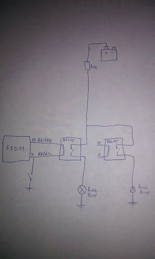
The optional toggle switch you see off of pin 3 is to bypass the FPDM and leave the pumps running full time. You'd use this when setting or checking base pressure with the key on engine off.
Last edited:
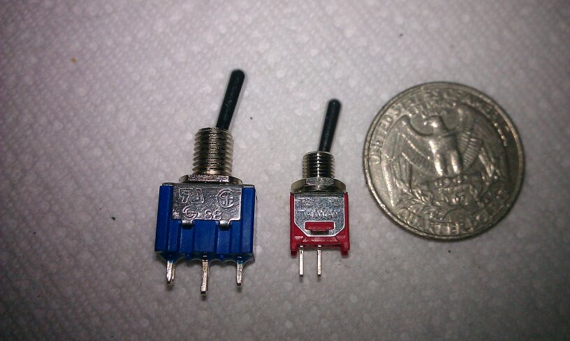
I did the little switch mod tonight. I tried to use the super micro switch you see next to the quarter but the neck on it was to short to even go through the plastic so I used the blue one. Turned out to be a non issue as it's hidden anyway.
See the switch hidden up there? This is by the driver's side amp.
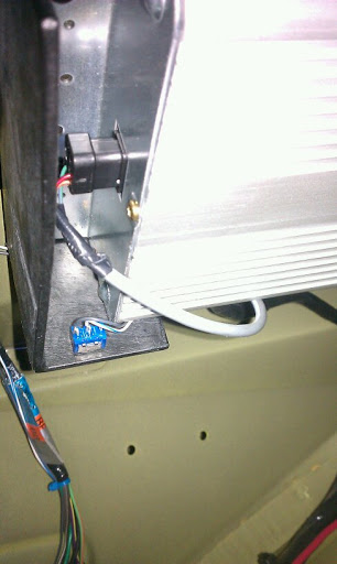
Ugly shot without the carpet back in there but see the switch hidden up there?
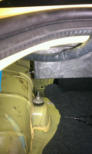
Works great too. When I need to set or check base pressure I just flip that switch and turn the key on engine off and the pumps just run continuously. Flip the switch back and it goes back to OEM style where the ECC controls the pumps.
See the switch hidden up there? This is by the driver's side amp.
Ugly shot without the carpet back in there but see the switch hidden up there?
Works great too. When I need to set or check base pressure I just flip that switch and turn the key on engine off and the pumps just run continuously. Flip the switch back and it goes back to OEM style where the ECC controls the pumps.
^^^^ Man that is awesome!!!
thanks for posting up the answer on the first page
:beer:
:beer:
My return setup has the fuel pumps come on as soon as the key is on and they just stay on but that's kinda ghetto. I'm wanting to get it work like OEM where key on means the pumps prime for a second or two and then go off. Crank the car and pumps are on, engine running pumps are on. If motor were to stall pumps go off after a second or two.
Anyone figure out how to make that happen? I was thinking of building an electronic circuit to do it. Use one of the outputs from the ECC that's only high when the engine is running to trigger it. If someone else has already done all this though no use in re-inventing the wheel. Thoughts, ideas?
Thanks
Malcolm
EDIT - I figured out the solution towards the end of page 2. Here it is for those searching and finding this thread.
SOLUTION:
OK when I first wired up my pumps return style my thought process was to remove the FPDM from the equation as it's no longer needed. Instead I took the DG/YE wire (pin 9) as everyone suggested and used it to power my relay. The downside of course is the pumps run continuously when the key is on regardless of engine running.
The signal wire from the ECC is the WH/R at the FPDM side (pin 1). It provides the correct times for the pumps to be on such as prime and then off when motor is off. It alone however is to weak to drive a relay.
So the solution is as simple as using the FPDM output that would normally drive a fuel pump to drive your relay. Use pin 10 & pin 3 to wire your relay. This way the ECC still tells the FPDM when the pumps should be turned on and the FPDM in turn activates your relay.
Pin 10 = BN/PK (normally fuel pump positive)
Pin 3 = RD/BK (normally fuel pump negative)
Note: you must use pin 3 to ground the relay coil (trigger) and not chassis ground or it does not work.
There you go guys!!
Malcolm
thanks for posting up the answer on the first page
:beer:
Any time man. I'm going to go back and update it some more later to make it more of a how to for others and also add the ground switch to pin 3 to the original first post as well as a wiring diagram to make it more complete
")
Malcolm, Thanks again for posting this. I wired up my fuel system and all is GOOD! I made a sketch that applies to my set-up that might help out some more... The colors apply to my relays....

Awesome diagram! This thread should definitely be made a sticky now!
Malcolm, Thanks again for posting this. I wired up my fuel system and all is GOOD! I made a sketch that applies to my set-up that might help out some more... The colors apply to my relays....

Sweet. Looks good. Did you opt for the additional override switch for setting and checking base fuel pressure? It just grounds pin 3 to chassis if you haven't already done it. It's in my earlier hand written wiring diagram I posted.
- Status
- Not open for further replies.
Users who are viewing this thread
Total: 4 (members: 0, guests: 4)

