Engine / Transmission harness questions

Black Venom 99

Member
Established Member
Joined
May 14, 2003
Messages
643
Location
Lemont Illinois
Hi everyone, need some help again.
I’m in the process of installing more wiring harnesses, and have a few questions.
-First question pertains to the transmission harness that contains the plugs for the output shaft speed control, and reverse lights plug (push pins to the driver side of trans, then runs up behind where top of trans meets the engine / behind lower intake against firewall.
The other end of this harness contains the two plugs for the O2 sensors.
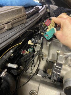
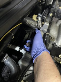
The larger plug which I labeled that has the inner red color (pic 1), I see it connects to the male end that is wired to a different loom that carries wiring for the injectors, throttle position sensor, and coil packs, and EGR connections. But the two harnesses also contain the green plugs, each on a separate harness (pic 1). Where do the green plugs connect?
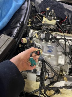
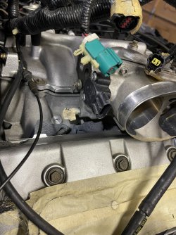
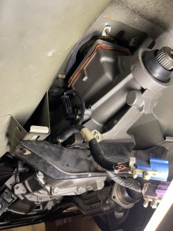
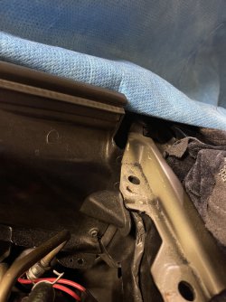
Pic 2 and 3, the black plug with the red inner portion (labeled “L”), where does this connect? Then the stud below that off the upper intake (labeled “F”), what connects this? It is right below where the idle speed control mounts.
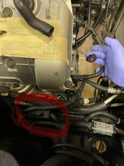
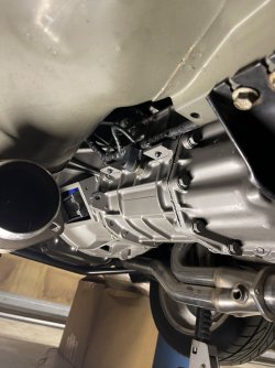
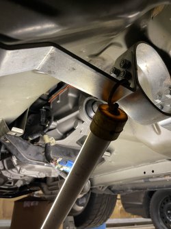
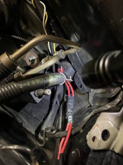
Lastly, pic 4 and 5, the harness (circled in red), is loomed to the plug in my hand, then routes down through the engine valley and ends up by the back of the lower intake (pic 5 - in my hand). Any direction on these two plugs?

I apologize if this is a bit much, but any help would be appreciated.

-Ronald.
 

Attachments

  • IMG_9756.jpeg
    IMG_9756.jpeg
    365.7 KB · Views: 62
  • IMG_9757.jpeg
    IMG_9757.jpeg
    387.6 KB · Views: 32
  • IMG_9758.jpeg
    IMG_9758.jpeg
    451 KB · Views: 30
  • IMG_9759.jpeg
    IMG_9759.jpeg
    335.9 KB · Views: 31
  • IMG_9760.jpeg
    IMG_9760.jpeg
    301.1 KB · Views: 29

52merc

Well-Known Member
Established Member
Joined
Nov 15, 2000
Messages
580
Location
Calgary, Alberta, Canada
The green connectors are for the front O2 sensors. Here is the information on the connectors for the O2 sensors:

C168 - Green housing, Left front, Wires - RD/BK, GY/RD, RD/YE, YE/LB
C169 - Green housing, Right front, Wires - GY/LB, GY/RD, RD/YE, RD/WH
C193 - Blue housing, Left rear, Wires - VT/LG, GY/RD, RD/YE, TN/YE
C196 - Violet housing, Right rear, Wires - RD/LG, GY/RD, RD/YE, WH/BK

The two left side O2 sensors should be on one harness leg. The blue colour of the rear sensor connector should tell you which green connector is for the left front. The other leg with the violet connector will be for the right side and that will determine the connector for the right front. Now, from your pictures it appears that both rear connectors could be black. Then you will need to look at the wire codes to determine left (driver side) from right (passenger side).

I'll have to go out and look for that other 2-pin connector.
 

52merc

Well-Known Member
Established Member
Joined
Nov 15, 2000
Messages
580
Location
Calgary, Alberta, Canada
The 2-pin connector in the picture with your gloved hand I believe is a fuel injector connector. Likely the right front injector (Inj-1) and should have a RD and a TN wire.
 

Black Venom 99

Member
Established Member
Joined
May 14, 2003
Messages
643
Location
Lemont Illinois
The green connectors are for the front O2 sensors. Here is the information on the connectors for the O2 sensors:

C168 - Green housing, Left front, Wires - RD/BK, GY/RD, RD/YE, YE/LB
C169 - Green housing, Right front, Wires - GY/LB, GY/RD, RD/YE, RD/WH
C193 - Blue housing, Left rear, Wires - VT/LG, GY/RD, RD/YE, TN/YE
C196 - Violet housing, Right rear, Wires - RD/LG, GY/RD, RD/YE, WH/BK

The two left side O2 sensors should be on one harness leg. The blue colour of the rear sensor connector should tell you which green connector is for the left front. The other leg with the violet connector will be for the right side and that will determine the connector for the right front. Now, from your pictures it appears that both rear connectors could be black. Then you will need to look at the wire codes to determine left (driver side) from right (passenger side).

I'll have to go out and look for that other 2-pin connector.
Thank you! A bit more for clarity (pics attached). My car has Kooks 1-3/4” long tubes, going into a Kooks 3” catless x-pipe, and EGR will be deleted. My headers have openings for an O2 on each one. So the pics attached hopefully help a bit more. But the green connectors are on different looms. One that is part of the transmission harness that leads up over the trans, and behind the lower intake. The other green one is part of the massive loom that holds all the plugs for injectors, coil packs, throttle position sensor, male side of trans connection, and EGR lines for upper intake.

Thanks as always Sir!
-Ronald.
 

Attachments

  • IMG_9769.jpeg
    IMG_9769.jpeg
    296.9 KB · Views: 23
  • IMG_9768.jpeg
    IMG_9768.jpeg
    238 KB · Views: 26
  • IMG_9770.jpeg
    IMG_9770.jpeg
    262.3 KB · Views: 26

Black Venom 99

Member
Established Member
Joined
May 14, 2003
Messages
643
Location
Lemont Illinois
The 2-pin connector in the picture with your gloved hand I believe is a fuel injector connector. Likely the right front injector (Inj-1) and should have a RD and a TN wire.
I found that after I posted. It’s off a different loom, that one connection for #1 injector. But the other plug that leads through the engine valley, and ends by the firewall, I’m stuck on.
 

52merc

Well-Known Member
Established Member
Joined
Nov 15, 2000
Messages
580
Location
Calgary, Alberta, Canada
The only 2 green EPC connectors I have information on are the front oxygen sensors and the only true way to determine left from right is by wire colours. They are on two different harnesses, the left is on harness 12B637 (that is just the base part number) and the right is on 15525.

BTW, the red sections on the inside of the connectors are called TPAs (Terminal Position Assurance). They keep the terminals locked in position. You pry the TPA out slightly and then you can reach in with a release tool (often a jeweler's screwdriver works) and release the terminal so you can remove it out the back of the housing.

Not all TPAs are red, but they usually are for EPC connectors which are the most prevalent type used on our cars.

Some connectors have a secondary lock on the disconnect release lever or button. These are often red as well and are known as CPAs (Connector Position Assurance). These are used to ensure the connector remains locked together (male to female) until the TPA is moved or removed depending on the connector design.

I assume with the catless exhaust that you are either using a tune or MIL eliminators to prevent the MIL (aka: CEL).
 

Black Venom 99

Member
Established Member
Joined
May 14, 2003
Messages
643
Location
Lemont Illinois
The 2-pin connector in the picture with your gloved hand I believe is a fuel injector connector. Likely the right front injector (Inj-1) and should have a RD and a TN wire.
I found that after I posted. It’s off a different loom, that one connection for #1 injector. But the other plug that leads through the engine valley, and ends by the firewall, I’m
The only 2 green EPC connectors I have information on are the front oxygen sensors and the only true way to determine left from right is by wire colours. They are on two different harnesses, the left is on harness 12B637 (that is just the base part number) and the right is on 15525.

BTW, the red sections on the inside of the connectors are called TPAs (Terminal Position Assurance). They keep the terminals locked in position. You pry the TPA out slightly and then you can reach in with a release tool (often a jeweler's screwdriver works) and release the terminal so you can remove it out the back of the housing.

Not all TPAs are red, but they usually are for EPC connectors which are the most prevalent type used on our cars.

Some connectors have a secondary lock on the disconnect release lever or button. These are often red as well and are known as CPAs (Connector Position Assurance). These are used to ensure the connector remains locked together (male to female) until the TPA is moved or removed depending on the connector design.

I assume with the catless exhaust that you are either using a tune or MIL eliminators to prevent the MIL (aka: CEL).
Thank you! I’ll address the evap line off the canister.
I don’t have use for those front O2 plugs (green ones), I will have to see how to go forward with them. The rears I will have to see as well, cause they are a decent length from reaching the collectors off the headers.
My exhaust is completely cat-less, and has tunes to accommodate no converters.
I’m just still stuck on that harness / loom that leads through the valley, and ends up by the back of the lower intake. The same loom that has the #1 injector harness tied into it. It also has wiring coming off of it that looks to lead into A/C components. The loom from my original post, pic 5.
-Ronald
 

Black Venom 99

Member
Established Member
Joined
May 14, 2003
Messages
643
Location
Lemont Illinois
"F" I believe is the EVAP cannister purge line. Here are the pictures from my car.
View attachment 1828304View attachment 1828305
That’s it, says gas/fuel on it which threw me off. But the silver component in between the line, I need to find, cause I see where my line breaks, to install that silver component. I have the two pieces mated together with a small plastic tube. Dont know why I removed it during disassembly.

-Ronald.
 

52merc

Well-Known Member
Established Member
Joined
Nov 15, 2000
Messages
580
Location
Calgary, Alberta, Canada
The PCM uses the front O2 sensors to control the fuel being injected into the engine. The rear O2 sensors are used to monitor the efficiency of the cats and will throw a MIL if the signal is out of range. I don't believe you can just not use all four O2 sensors, even with tune.
 

Black Venom 99

Member
Established Member
Joined
May 14, 2003
Messages
643
Location
Lemont Illinois
The PCM uses the front O2 sensors to control the fuel being injected into the engine. The rear O2 sensors are used to monitor the efficiency of the cats and will throw a MIL if the signal is out of range. I don't believe you can just not use all four O2 sensors, even with tune.
I’m gonna have to do a bit of research to see what I need to do.
Do you have any idea on picture #5 I posted?
You’ve been a wealth of knowledge, and I appreciate it.
 

Black Venom 99

Member
Established Member
Joined
May 14, 2003
Messages
643
Location
Lemont Illinois
The PCM uses the front O2 sensors to control the fuel being injected into the engine. The rear O2 sensors are used to monitor the efficiency of the cats and will throw a MIL if the signal is out of range. I don't believe you can just not use all four O2 sensors, even with tune.
I also just went in the basement and checked my x-pipe, it has the threaded inserts for the O2 sensors, as well as the ones on each collector, off the headers. So four total, like I had with my previous setup before I began the build.
Both green O2’s, especially the one separate from the trans loom, both won’t be near reaching the collector off each header.
 

Black Venom 99

Member
Established Member
Joined
May 14, 2003
Messages
643
Location
Lemont Illinois
I also just went in the basement and checked my x-pipe, it has the threaded inserts for the O2 sensors, as well as the ones on each collector, off the headers. So four total, like I had with my previous setup before I began the build.
Both green O2’s, especially the one separate from the trans loom, both won’t be near reaching the collector off each header.
I spoke too soon, SVE makes extensions for the upstream sensors, which is what I need. They are 15” in length to allow connection to the collectors. The rears after the trans will reach the x-pipe.
 

52merc

Well-Known Member
Established Member
Joined
Nov 15, 2000
Messages
580
Location
Calgary, Alberta, Canada
Picture 5 has a black 8-way connector in your hand. If it has 4 wires going to it (BK/PK, DG/OG, LG/WH, and YE/WH) then it is inline connector C1008 which is for the wiper motor. There should be the other half behind the lower cowl cover. Here is a picture of the harness going in behind the cover. That leg of the harness branches off of the harness that passes through the firewall just below where this picture is cut off.

IMG_0496.jpeg
 

Black Venom 99

Member
Established Member
Joined
May 14, 2003
Messages
643
Location
Lemont Illinois
Picture 5 has a black 8-way connector in your hand. If it has 4 wires going to it (BK/PK, DG/OG, LG/WH, and YE/WH) then it is inline connector C1008 which is for the wiper motor. There should be the other half behind the lower cowl cover. Here is a picture of the harness going in behind the cover. That leg of the harness branches off of the harness that passes through the firewall just below where this picture is cut off.

View attachment 1828406
Is that picture the driver side corner off the firewall?
 

Black Venom 99

Member
Established Member
Joined
May 14, 2003
Messages
643
Location
Lemont Illinois
Is that picture the driver side corner off the firewall?
Should be. Here is mine, sorry, a bit dusty. That wire coming out of the firewall cover goes down into the the uni-body (pics attached), and also has a wire harness coming out of the loom that is plugged into the master cylinder.
 

Attachments

  • IMG_9823.jpeg
    IMG_9823.jpeg
    337.4 KB · Views: 24
  • IMG_9824.jpeg
    IMG_9824.jpeg
    298.7 KB · Views: 21

Users who are viewing this thread


Top