I am attempting to install an PLX SM-AFR wideband. I will be replacing a front sensor and using the simulated output to feed the PCM the narrowband signal and will install a resistor on the heater line to simulate "heating" of the sensor. However this is made difficult by my lack of knowledge as to which wire is which on the stock harness to the sensor. If anyone has this knowledge I would greatly appreciate it!
You are using an out of date browser. It may not display this or other websites correctly.
You should upgrade or use an alternative browser.
You should upgrade or use an alternative browser.
Anyone have a wiring diagram for the O2 sensors?
- Thread starter speedoflife
- Start date
Anybody got a clue?
Two white wires. One gray. One black.
Two white wires. One gray. One black.
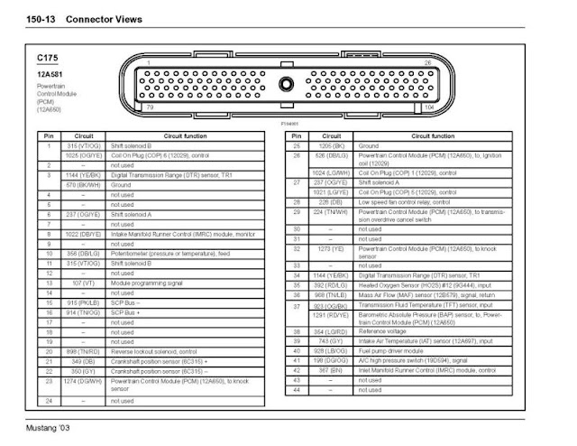
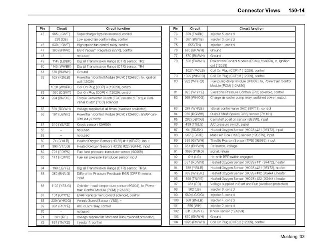
is this what your looking for?

I appreciate the diagram but that wasn't exactly what I needed. Close but that just doesn't label the individual pins on the connector relative to what's on the car. Thanks though!!
Why exactly do you recommend against splicing besides the obvious importance of the information transmitted (what determines fuel data)? The connection adds some resistance but even when measurements matter in the millivolts, the splice wouldn't add enough resistance to make a difference. There is a delay added by the increased amount of circuitry but it is again negligible. Just because it's different doesn't make it any less "right." A copper wire used to transmit voltage is a copper wire. Unless I'm missing something...?
Edit: got the info I needed:
http://www.svtperformance.com/forum...nsor-issues-after-your-long-tube-install.html
Last edited:
Here's ECU pinout
I've done exactly what you're trying to do on my Turbo'd Honda. The difference was it only had a single narrow band for the 4 cylinders. So when I built the new exhaust system for the turbo I only put a single bung in there and used the wideband. Initially I used the simulated narrow band output for the ECU but once I switched to an aftermarket ECU setup it was able to read the wideband and required no narrow band or narrow band simulation which was awesome.
Anyhow my only concern with doing it on the Cobra is you have two banks of cylinders and two narrow band sensors, one per bank. I have little faith that the sensor and wideband you have will produce the exact same narrow band voltage as the other factory sensor in the opposite bank. I think you'll create a condition where the ECU is constantly flapping a tiny amount trying to compensate between the differences in them.
If you've ever played around with a number of widebands you'll find they don't even read the same. You stick in brand X and make a few pulls and see it's reading 11.7 AF. Pull it out and install a different brand and it says you're 11.9 on each pull. They're all in the ball park but not exact. It's why I don't tune my car right at 12.0 in case my stupid wideband is telling me 12.0 but it's really 12.2 or worse.
Users who are viewing this thread
Total: 2 (members: 0, guests: 2)

