HI all, it seems like everything been cool down a lot here / so quiet on the S197 Shelby GT500 forum lately due to the arrival of the new 2020 Shelby GT500.
So I would like to share some of my lately work on my KB 3.6 supercharger inlet manifold design work / development / adventure. Hopefully this would bring up some more discussions and excitement in the S197 Shelby GT500 forum community. Since I will attached lots of pictures so I will split it into part 1 & 2.
First of all, I would like to give a big "Thank You" to Jim Bell at Kenne Bell who have help me so much on the actually dimensions of their KB 3.6 supercharger main body. He is kind enough to have his guy from Sweden email me the actual 3.6 supercharger CAD file so I can match all the required dimensions.
Originally, I was planning to upgrade my VMP Gen-2 (NOT the Gen-2R version) to the VMP Gen-3 supercharger when VMP introduce their new blower 2 - 3 years ago. But I have always wanted to try something new especially been went thru both VMP Gen-1 and VMP Gen-2 blowers from stock M122 supercharger. So I bought a used KB 3.6 L/C blower from a forum member here and this is where my inlet manifold work started.
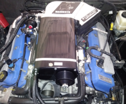
The reason Kenne Bell incorporated a big depression at the rear of passenger side inlet manifold is to install the stock EGR valve at the stock location using stock EGR tube. They need to maintain the EGR valve to pass smog requirements. But due to the big depression it actually obstruct (but not blocking) the air flow. Also, the front inlet short turn wall where it meets the throttle body to the driver side rotor is pretty much the same situation - KB wanted to mount their throttle body as close to stock location as possible. But this leads to another air flow obstruction (but not blocking) again. Below are some pictures of the KB 3.6 Mammoth inlet shows the EGR valve depression and the front inlet short turn wall.

View attachment 1672656

I started looking at the KB Mammoth inlet and see where I can improve it. Unlike some states, where I live has NO emission test requirements for license plate renewal so the first thing I did is to removes the EGR depression. The outcome is much better BUT still does NOT look good / right to the way I wanted. Below are some pictures of the modified Mammoth inlet without the EGR depression.


The front inlet short turn wall where it meets the throttle body is the worst area to modify. I know some guys have added weld at that area and try to port internally as much as possible. But I can tell you one thing for sure, there is NO WAY you can eliminates that "S turn" completely without redesigning that area. A CAD model can tell you everything / cannot hide anything. If you put a 90 degree straight edge and measure the distance between "S turn" to the closest outer most opening of the inlet flange, there is quite a bite of distance and just not enough room to add that much weld. Below are pictures of added weld to the front short turn walls try to eliminates the obstruction.

So I would like to share some of my lately work on my KB 3.6 supercharger inlet manifold design work / development / adventure. Hopefully this would bring up some more discussions and excitement in the S197 Shelby GT500 forum community. Since I will attached lots of pictures so I will split it into part 1 & 2.
First of all, I would like to give a big "Thank You" to Jim Bell at Kenne Bell who have help me so much on the actually dimensions of their KB 3.6 supercharger main body. He is kind enough to have his guy from Sweden email me the actual 3.6 supercharger CAD file so I can match all the required dimensions.
Originally, I was planning to upgrade my VMP Gen-2 (NOT the Gen-2R version) to the VMP Gen-3 supercharger when VMP introduce their new blower 2 - 3 years ago. But I have always wanted to try something new especially been went thru both VMP Gen-1 and VMP Gen-2 blowers from stock M122 supercharger. So I bought a used KB 3.6 L/C blower from a forum member here and this is where my inlet manifold work started.
The reason Kenne Bell incorporated a big depression at the rear of passenger side inlet manifold is to install the stock EGR valve at the stock location using stock EGR tube. They need to maintain the EGR valve to pass smog requirements. But due to the big depression it actually obstruct (but not blocking) the air flow. Also, the front inlet short turn wall where it meets the throttle body to the driver side rotor is pretty much the same situation - KB wanted to mount their throttle body as close to stock location as possible. But this leads to another air flow obstruction (but not blocking) again. Below are some pictures of the KB 3.6 Mammoth inlet shows the EGR valve depression and the front inlet short turn wall.
View attachment 1672656
I started looking at the KB Mammoth inlet and see where I can improve it. Unlike some states, where I live has NO emission test requirements for license plate renewal so the first thing I did is to removes the EGR depression. The outcome is much better BUT still does NOT look good / right to the way I wanted. Below are some pictures of the modified Mammoth inlet without the EGR depression.
The front inlet short turn wall where it meets the throttle body is the worst area to modify. I know some guys have added weld at that area and try to port internally as much as possible. But I can tell you one thing for sure, there is NO WAY you can eliminates that "S turn" completely without redesigning that area. A CAD model can tell you everything / cannot hide anything. If you put a 90 degree straight edge and measure the distance between "S turn" to the closest outer most opening of the inlet flange, there is quite a bite of distance and just not enough room to add that much weld. Below are pictures of added weld to the front short turn walls try to eliminates the obstruction.