I think you are mistaken. The connector in Picture #5 appears to be an 8-way. The knock sensor connector is similar in design and looks, but is only a 2-way connector. What are the wire colours going to that connector?
You are using an out of date browser. It may not display this or other websites correctly.
You should upgrade or use an alternative browser.
You should upgrade or use an alternative browser.
Engine / Transmission harness questions
- Thread starter Black Venom 99
- Start date
Gray, yellow, red, blue, and blackI think you are mistaken. The connector in Picture #5 appears to be an 8-way. The knock sensor connector is similar in design and looks, but is only a 2-way connector. What are the wire colours going to that connector?
Then lastly, this plug in my hand (pic attached). It is on the same loom as the one green O2 sensor (opposite of the O2 that is on the trans harness), and the wires for ISC, TPS, injectors, and coil packs.Gray, yellow, red, blue, and black
Sorry. Forgot attachment.Then lastly, this plug in my hand (pic attached). It is on the same loom as the one green O2 sensor (opposite of the O2 that is on the trans harness), and the wires for ISC, TPS, injectors, and coil packs.
Attachments
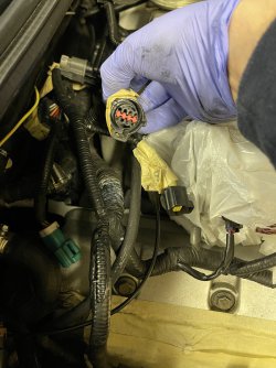
I believe that is inline connector C139. It matches the pinout positions in the picture.
Pin-1 is BK (Black) Crankshaft Position Sensor Shield
Pin-2 is not used
Pin-3 is DB (Dark Blue) CKP Sensor Positive [+]
Pin-4 is TN (Tan) Fuel Injector-1 PCM Switched Ground
Pin-5 is not used
Pin-6 is not used
Pin-7 is RD (Red) Central Junction Box Fuse-2 (20 A) Hot in Start/Run Power for Fuel Injector-1
Pin-8 is GY (Gray) CKP Sensor Negative [-]
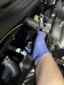
I believe this leg of the harness in routed under the intake manifold and attaches to the male plug behind the alternator. I'll take a picture of where I think it goes.
Pin-1 is BK (Black) Crankshaft Position Sensor Shield
Pin-2 is not used
Pin-3 is DB (Dark Blue) CKP Sensor Positive [+]
Pin-4 is TN (Tan) Fuel Injector-1 PCM Switched Ground
Pin-5 is not used
Pin-6 is not used
Pin-7 is RD (Red) Central Junction Box Fuse-2 (20 A) Hot in Start/Run Power for Fuel Injector-1
Pin-8 is GY (Gray) CKP Sensor Negative [-]
I believe this leg of the harness in routed under the intake manifold and attaches to the male plug behind the alternator. I'll take a picture of where I think it goes.
Here is my picture. I believe C139 is inside the protective sleeve.

I’ve attached a pics (below). Matches your pic, nothing plugs in behind the alternator, and the harness in my hand is for injector number 1. Same harness that routes under the intake, and back to the plug I’m stuck on. But my second pic is from the Ford shop manual, and it 99% matches that wire loom I’m speaking of. I may be off, and stumped.
I appreciate the help Sir.
Attachments

And that same loom, perfectly matches going into the AC compressor, crankshaft sensor, electronic control sensor, fuel injector #1, then routes by the alternator and then down under the lower intake within the engine valley.I’ve attached a pics (below). Matches your pic, nothing plugs in behind the alternator, and the harness in my hand is for injector number 1. Same harness that routes under the intake, and back to the plug I’m stuck on. But my second pic is from the Ford shop manual, and it 99% matches that wire loom I’m speaking of. I may be off, and stumped.
I appreciate the help Sir.
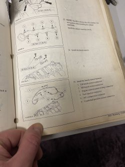
Without pulling apart my car I'm not sure I can offer you much more help. I believe Item 3 in the bottom frame labeled "engine control sensor wiring connector" is indeed C139 and the other half of the connector in you Picture #5. It must connect under the intake manifold. I can't say for sure as I've never had the intake manifold off the engine.
Item #3 “electronic control connector” from the shop manual is already connected to its other half (connects right in front of the passenger side strut tower, sits below the factory air box). Then routes nicely to the AC compressor, crankshaft sensor, injector #1, then down into the valley below the intake.Without pulling apart my car I'm not sure I can offer you much more help. I believe Item 3 in the bottom frame labeled "engine control sensor wiring connector" is indeed C139 and the other half of the connector in you Picture #5. It must connect under the intake manifold. I can't say for sure as I've never had the intake manifold off the engine.
I’m most likely going to pull the upper and lower intake off so I can look further.
My last pic I posted, (post #24), do you have an idea on that harness? It’s off the loom that carries harnesses for ISC, TPS, injectors, coil packs, and one of the green O2 sensor plugs.
Can’t stress enough how much I thank you for the help you’ve given Sir.
-Ronald
See my Post #25.
I've been trying to follow this thread .
Hard on here,but looking at these couple of pics I see c139 more under throttle body area .
How close are these actually,
Page 1
 acrobat.adobe.com
Page 2
 acrobat.adobe.com
Page 3
 acrobat.adobe.com
Page trans
 acrobat.adobe.com
Hard on here,but looking at these couple of pics I see c139 more under throttle body area .
How close are these actually,
Page 1
Adobe Acrobat
Page 2
Adobe Acrobat
Page 3
Adobe Acrobat
Page trans
Adobe Acrobat
The trans harness (in your last adobe file), I have that look accounted for, and all plugs (male and female) are set. The harnesses (I’ll repost the two below), are the ones I’m stuck on. The circular one comes right out of the valley underneath the intakes by the firewall.I've been trying to follow this thread .
Hard on here,but looking at these couple of pics I see c139 more under throttle body area .
How close are these actually,
Page 1
Adobe Acrobat
Page 2
Adobe Acrobat
Page 3
Adobe Acrobat
Page trans
Adobe Acrobat
The larger one (second pic below off this post), is off a different loom (loom that houses plugs for throttle positioning sensor, idle speed control, injectors minus #1 injector, left bank O2 plug, and coil pack plugs).
The smaller circular one has no other matching plugs near it to connect too, and is mostly under the lower intake in the engine valley.
The larger one be associated when I begin to add in fuel rails (but I’m installing a return fuel system with different fuel rails, injectors, etc. Stock system won’t do.)
Also, all plugs near or next to the throttle body have their partnered ends accounted for.
The two pics below are the ones I’m stumped on.
Thanks to both you Gentleman for the help.
-Ronald
Attachments

The trans harness (in your last adobe file), I have that look accounted for, and all plugs (male and female) are set. The harnesses (I’ll repost the two below), are the ones I’m stuck on. The circular one comes right out of the valley underneath the intakes by the firewall.
The larger one (second pic below off this post), is off a different loom (loom that houses plugs for throttle positioning sensor, idle speed control, injectors minus #1 injector, left bank O2 plug, and coil pack plugs).
The smaller circular one has no other matching plugs near it to connect too, and is mostly under the lower intake in the engine valley.
The larger one be associated when I begin to add in fuel rails (but I’m installing a return fuel system with different fuel rails, injectors, etc. Stock system won’t do.)
Also, all plugs near or next to the throttle body have their partnered ends accounted for.
The two pics below are the ones I’m stumped on.
Thanks to both you Gentleman for the help.
-Ronald
Adobe Acrobat
Step 27 plug?
Looks like on back of engine,
Plug 3 you show on that manual photo
I see c1008
139,119 all looking alike but pinned different for items ,and location of plugs .
Pics from post #33, are the two I’m stuck on. The pics from post #27, the first one is injector # 1, which I’m good. The pic from the shop manual, all plugs line up perfectly, and I’m stuck on the one plug from post #33, first pic that has the circular connector. It exits from the back of the lower intake / engine valley, near the firewall. To me it seems that I missed plugging in a knock sensor harness. When I slightly pull on the loom (loom from the picture of my Ford shop manual-post 27) exiting the front of the engine valley, that circular plug at the back of the valley wiggles.Adobe Acrobat
acrobat.adobe.com
Step 27 plug?
Looks like on back of engine,
Plug 3 you show on that manual photo
I see c1008
139,119 all looking alike but pinned different for items ,and location of plugs .
-Ronald.
To funny,,like I said hard on here.Pics from post #33, are the two I’m stuck on. The pics from post #27, the first one is injector # 1, which I’m good. The pic from the shop manual, all plugs line up perfectly, and I’m stuck on the one plug from post #33, first pic that has the circular connector. It exits from the back of the lower intake / engine valley, near the firewall. To me it seems that I missed plugging in a knock sensor harness. When I slightly pull on the loom (loom from the picture of my Ford shop manual-post 27) exiting the front of the engine valley, that circular plug at the back of the valley wiggles.
-Ronald.
Your pics of connections in reply #33.
Yes. I get that.
Open what I posted. Step 27
Not your reply #27.
Here it shows where that larger plug sits. On back of engine next to heater core line into head
Than a couple steps later scrolling past 27 you will see that harness you posted
From wiring
Knock sensor on harness shows c1011.
Knock sensor connectors c166/c174
To c1011 square connector
6 circuits
Than to pcm c 294.
C1011
Has right knock
Circuits 310 yellow/red
1273 yellow
Left knock
Circuit 311 DG/VT
1274dg/wh
Than Ac coil
Circuit
347 black/yellow
1205 black
Than when I look more
C139 goes to c104 than to pcm c294
Can you give the actual color of wires on those 2 plugs
Going through what connection views the 99 manual gives
I see 4 different areas this type of connector was used in engine bay
I'm using the link I shared with you.
I have 2003 on CD ,mach 1 is looking close to the same just different connection number but same circuits
Gentleman, I want to thank you for your help! All the aforementioned harnesses are accounted for and secured as well as organized.To funny,,like I said hard on here.
Your pics of connections in reply #33.
Yes. I get that.
Open what I posted. Step 27
Not your reply #27.
Here it shows where that larger plug sits. On back of engine next to heater core line into head
Than a couple steps later scrolling past 27 you will see that harness you posted
From wiring
Knock sensor on harness shows c1011.
Knock sensor connectors c166/c174
To c1011 square connector
6 circuits
Than to pcm c 294.
C1011
Has right knock
Circuits 310 yellow/red
1273 yellow
Left knock
Circuit 311 DG/VT
1274dg/wh
Than Ac coil
Circuit
347 black/yellow
1205 black
Than when I look more
C139 goes to c104 than to pcm c294
Can you give the actual color of wires on those 2 plugs
Going through what connection views the 99 manual gives
I see 4 different areas this type of connector was used in engine bay
I'm using the link I shared with you.
I have 2003 on CD ,mach 1 is looking close to the same just different connection number but same circuits
Another question if I may, as you’ve both been a huge help. From the main power harness that comes off the fuse box, as it comes down the drivers side, the oil pressure switch stems off the loom (all set there), then leads off to a ground ring terminal…which is my question.
Does that ring terminal ground to the studded bolt off the engine mount, drivers side?
Thanks again!
-Ronald.
My 03 had the ground for negative on that stud along with a braided wire that went to frameGentleman, I want to thank you for your help! All the aforementioned harnesses are accounted for and secured as well as organized.
Another question if I may, as you’ve both been a huge help. From the main power harness that comes off the fuse box, as it comes down the drivers side, the oil pressure switch stems off the loom (all set there), then leads off to a ground ring terminal…which is my question.
Does that ring terminal ground to the studded bolt off the engine mount, drivers side?
Thanks again!
-Ronald.
Thanks Sir! I was 99% on that. Just don’t have a braided wire coming off that loom, just the ground terminal.My 03 had the ground for negative on that stud along with a braided wire that went to frame
Appreciate the help!
-Ronald
Wonder if that braided wire was an addition for 03/04?My 03 had the ground for negative on that stud along with a braided wire that went to frame
Users who are viewing this thread
Total: 3 (members: 0, guests: 3)

