It's widely known that the OEM audio system in the 2012/2013 Boss Mustang is the cheapest and lowest quality available for a Mustang. Not knocking Ford for this, this model is touted as 'a race car with a license plate', so anyone who expects good tunes from the factory will be in for a big disappointment. The speakers are suitable for AM radio only, and the head unit lacks power. The sad part is, if you just replace all of the 6x8 speakers with any decent coaxial, you will quickly discover that the signal quality and lack of power requires a complete replacement of the head unit.
Once you know you need to replace the head unit, finding a replacement dash panel is required. I really wasn't too impressed with the appearance of the Metra & Scoche kits, and was glad to see the iDatalink Maestro kit hit the market. I was critical of the initial cost when this was released, but I got lucky and snagged the ADS-KIT-MUS1 and RR module for 249$ new/shipped from eBay. I couldn't be happier with the quality, fit and finish. Props the manufacturer, iDatalink really impresses with their product line, engineering, web site, and attention to detail. The fact that we have 12v Guy here to answer questions and offer help and advice is a much appreciated bonus.
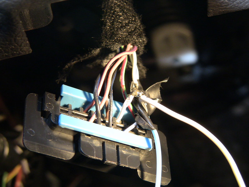
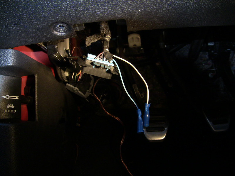
Since I had tried the incremental upgrade approach - replace all speakers - suck - add PAC Audio interface to feed amplifier - more suck, fail - it was time to go whole hog. So the time came to put together a list of components and materials. Since I had already installed an old, scratch that, *ancient* Yamaha 4ch amp to power the JL Audio coaxials, I already have the amp install kit installed. Now it's one inline fuse and wires run through the firewall from the pre-cut hole in the firewall thanks to the sound tube delete kit grommet. My arm is sore from patting myself on the back for running TWO power wires, as I knew I would be adding a second amp. I figured I could address the need for a 2nd fuse later (now if recommended), but at least that part is done.
Another reason my shoulder is sore, is that I came up with an innovative way to temporarily mount the amplifier in the trunk. I got some industrial strength tie wraps, and looped them around the rear deck and seat area. From those I was able to suspend the amp by running another set of tie wraps through the 4 corner mount holes of the amp through the loops created by the 1st set of tie wraps around the body panels. The beauty of this setup is that you can adjust the tension of the wraps as needed. A piece of foam can be wedged between the rear deck to prevent the amp from bouncing upward in event of a hard bump. This setup is also quite handy as you can snip the secondary set of ties to 'uninstall' the amp so you can make adjustments as needed, and then re-tie. I may copy the plywood and angle bracket setup shown in clucas build thread for my amps.
On a side note, using this old amp wasn't such a hot idea. After a few weeks use, one of the channels started to fail. As a side effect, Sync voice prompts ceased to function, even after yanking the battery cable and performing a factory reset. Once the faulty amp was removed, Sync functions returned.
The equipment list (links provided for reference only, all gear purchased through Amazon, Parts-Express, or Ebay);
Kenwood DNX690HD
http://www.kenwoodusa.com/Car_Entertainment/eXcelon/Mobile_Video_n_Navigation/DNX690HD
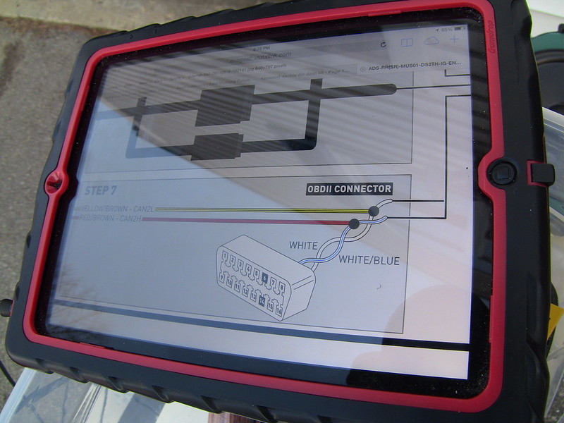
iDatalink ADS-KIT-MUS1 & RR Module
http://maestro.idatalink.com/search...013&vehicle_model_id=66&vehicle_audio_id=8478
Crunch Audio DRA 1450.4 4x175w
http://www.sonicelectronix.com/pictures_new.php?id=67958&picture_id=1300073
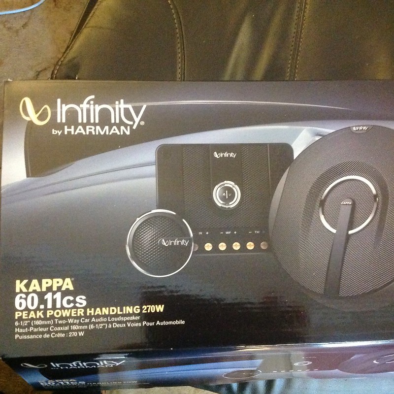
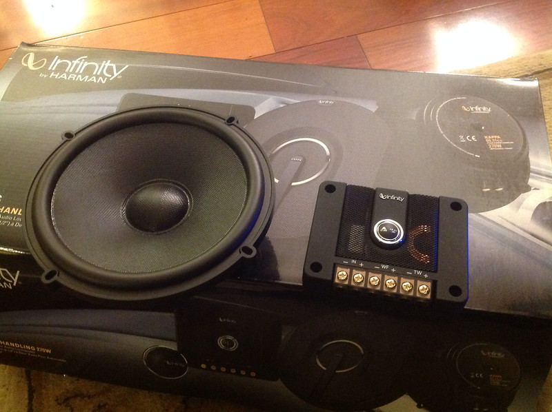
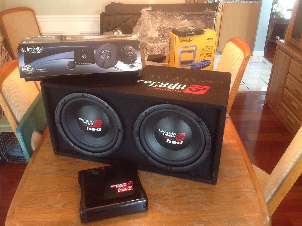
Infinity Kappa 6.5 60.11cs
http://www.sonicelectronix.com/pictures_new.php?id=60700&picture_id=-1
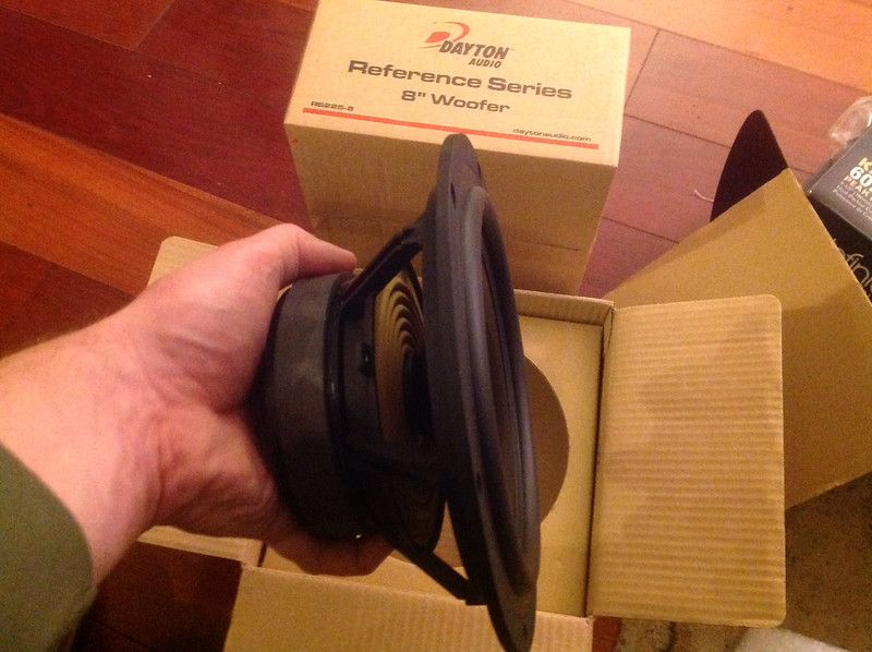
Dayton Audio RS-255-8
http://www.parts-express.com/dayton-audio-rs225-8-8-reference-woofer--295-356
Cerwin Vega HEDBK212
http://www.sonicelectronix.com/item_39705_Cerwin-Vega-HEDBK212.html
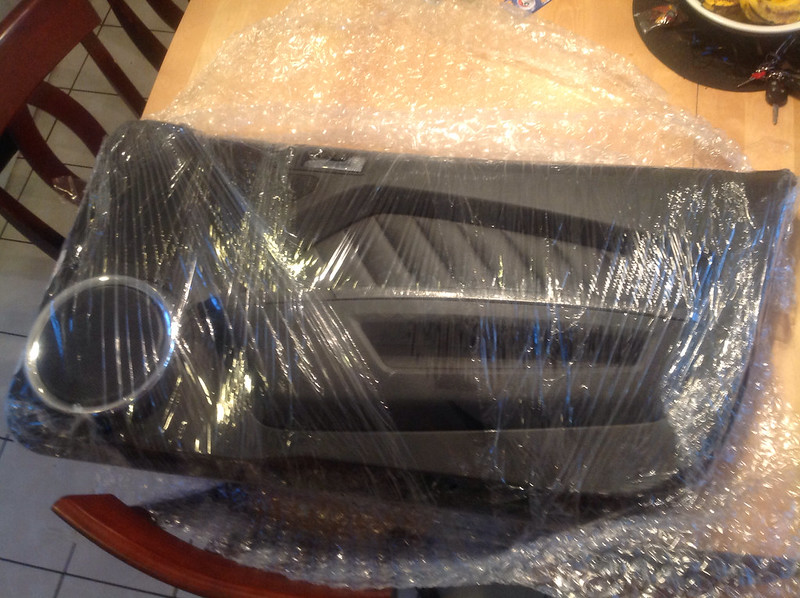
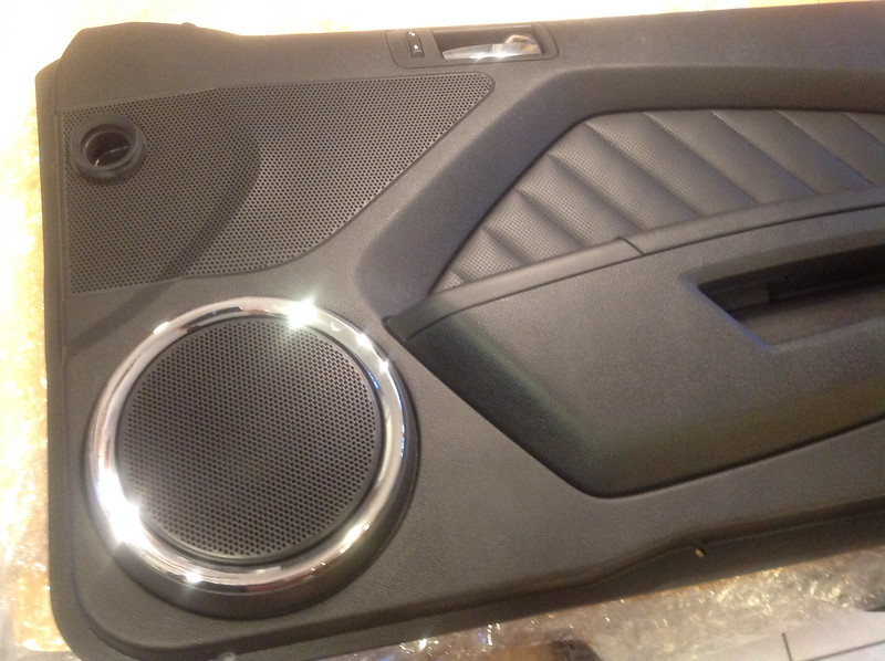
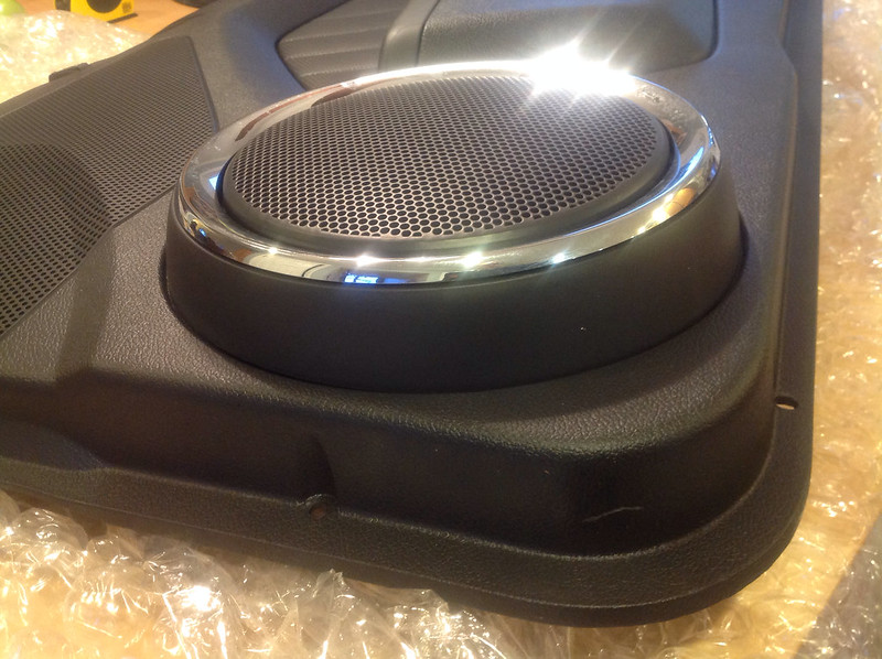
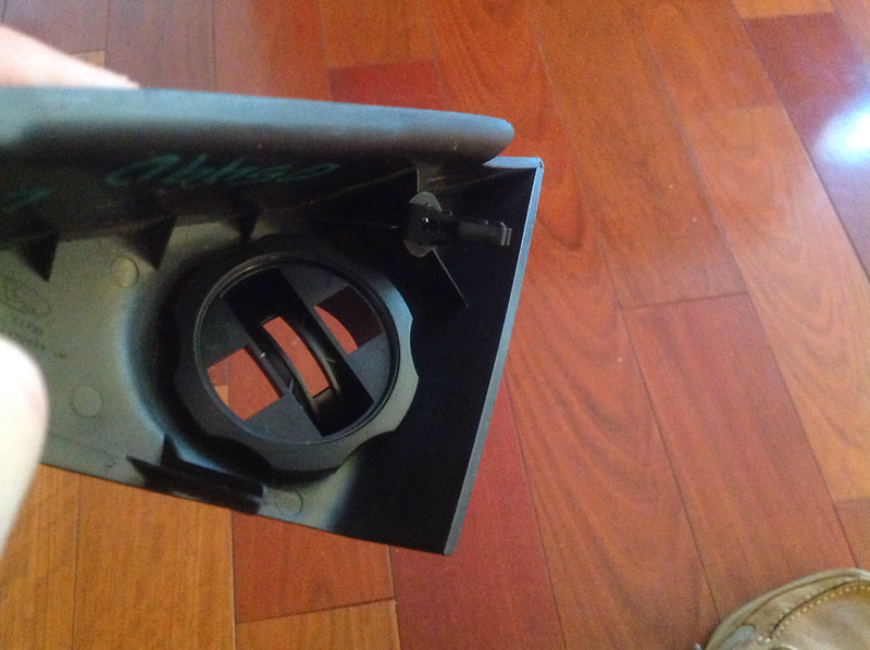
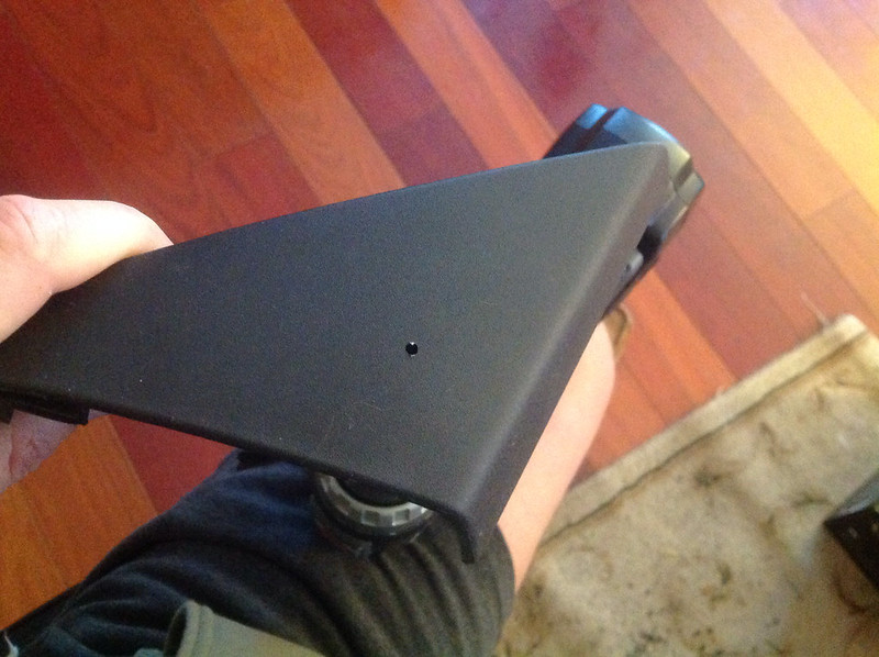
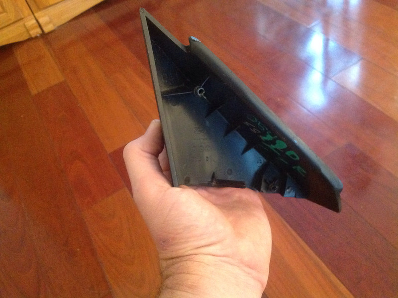
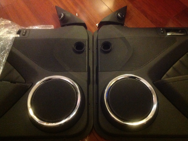
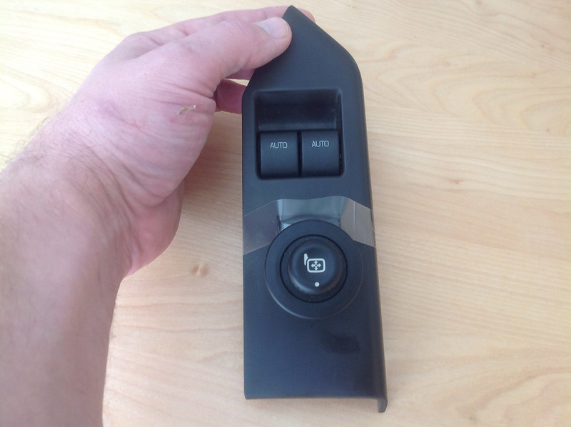
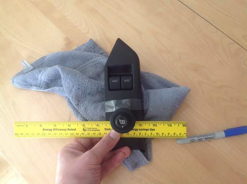
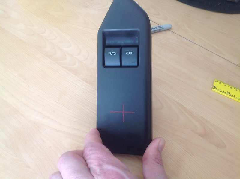
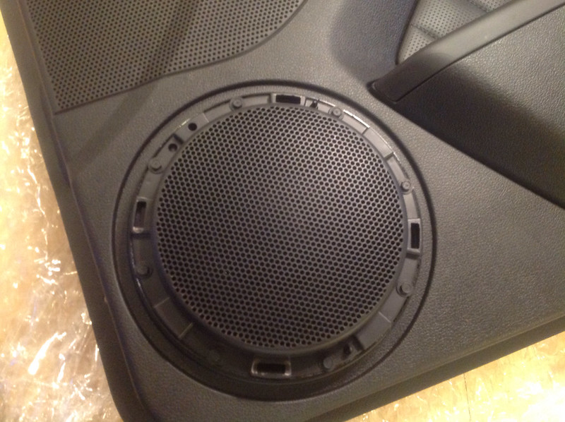
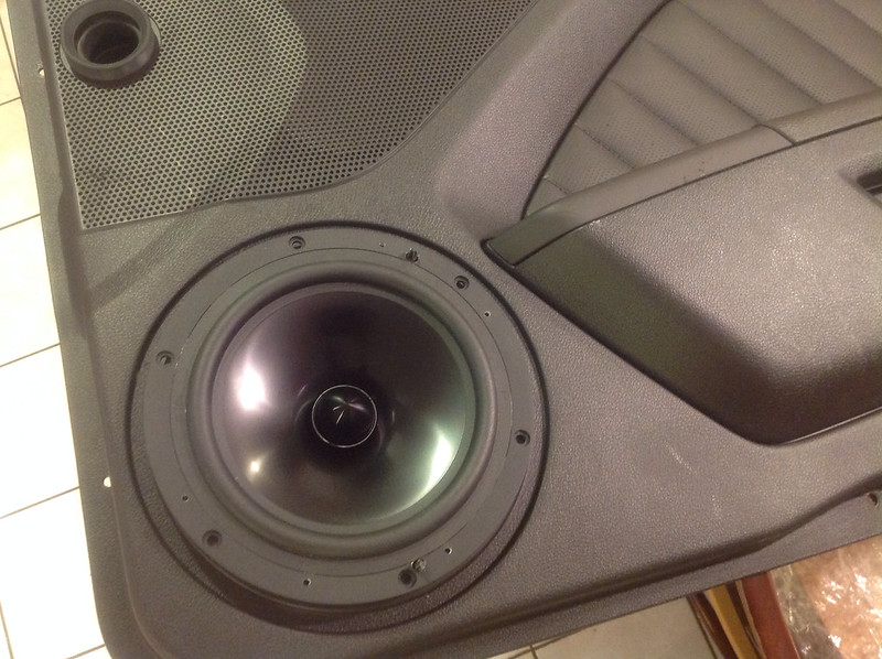
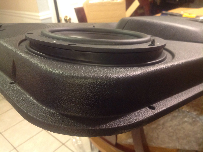
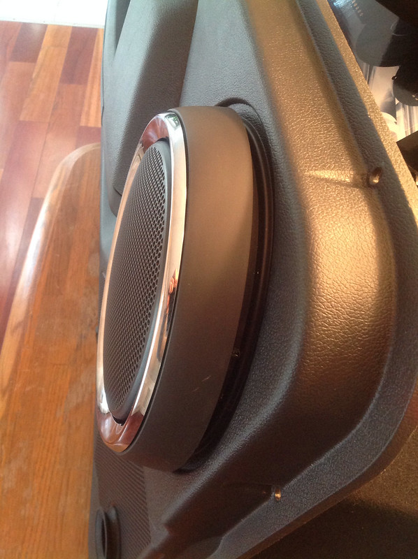
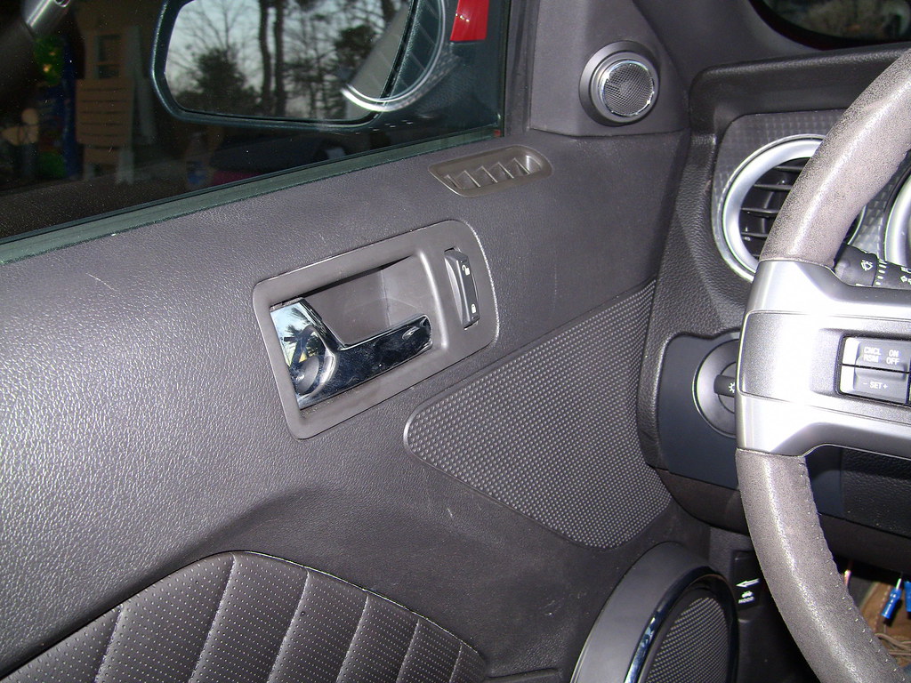
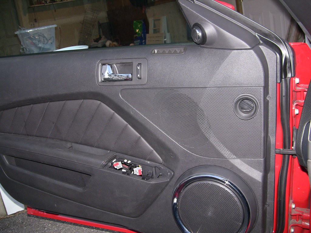
When I bought my Boss, I knew I would be upgrading the audio, so I purchased a pair of GT Premium door panels, complete with all hardware and switches.


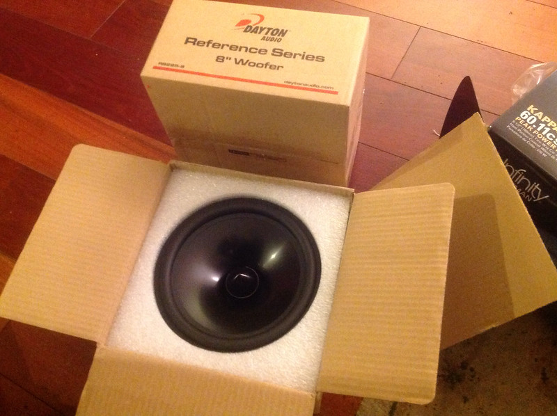
As I was having a hard time finding some JL ZR-800s for a decent price, I picked up a pair of Dayton Audio RS-255s. Great reviews and feedback on these, and I'm very happy with the pair of 10" Dayton Audio powered subwoofers, so I'm liking the brand so far.


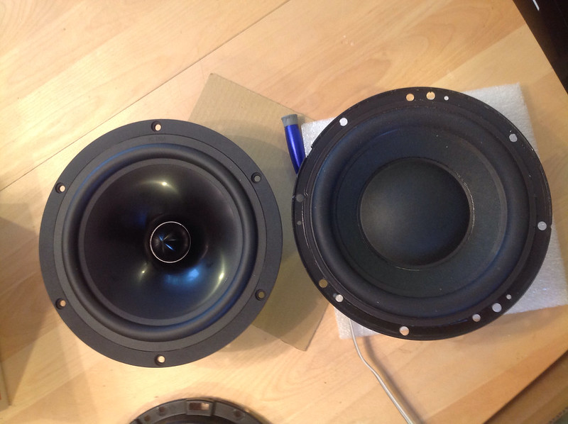
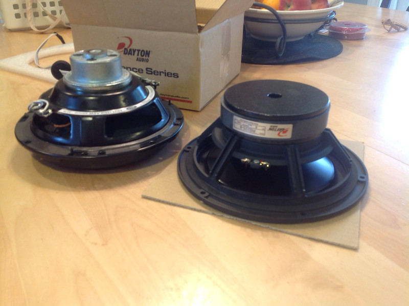
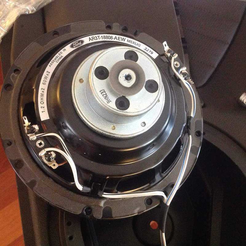
No comparison to the wimpy & cheap stock speaker.


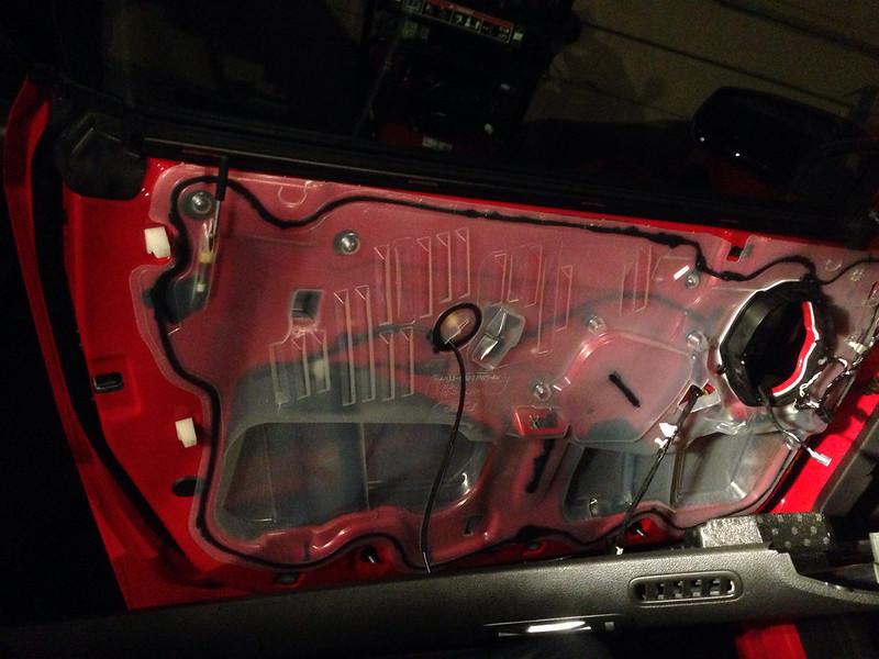
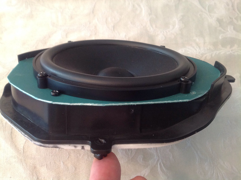
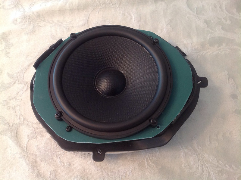
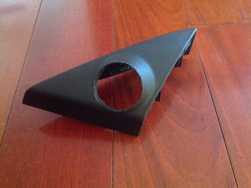
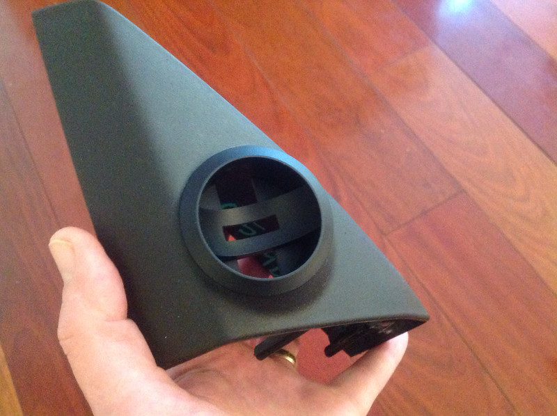
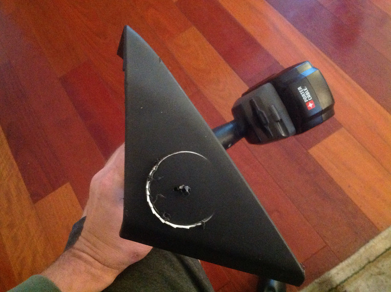
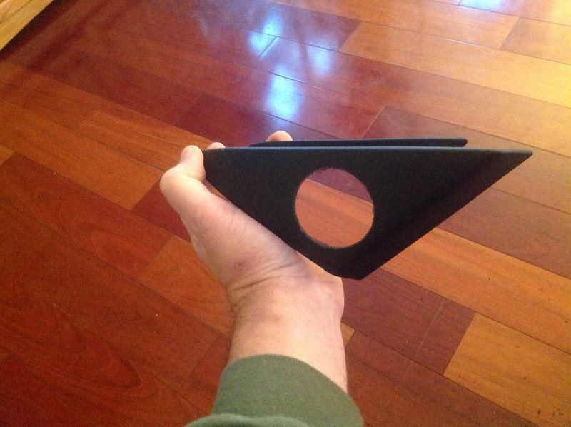
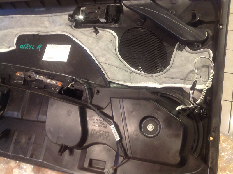
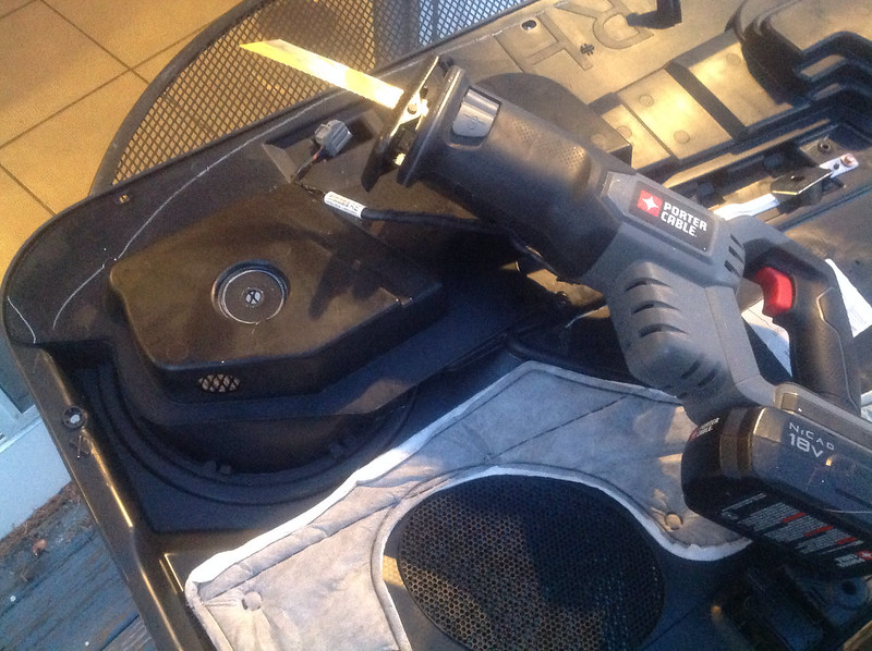
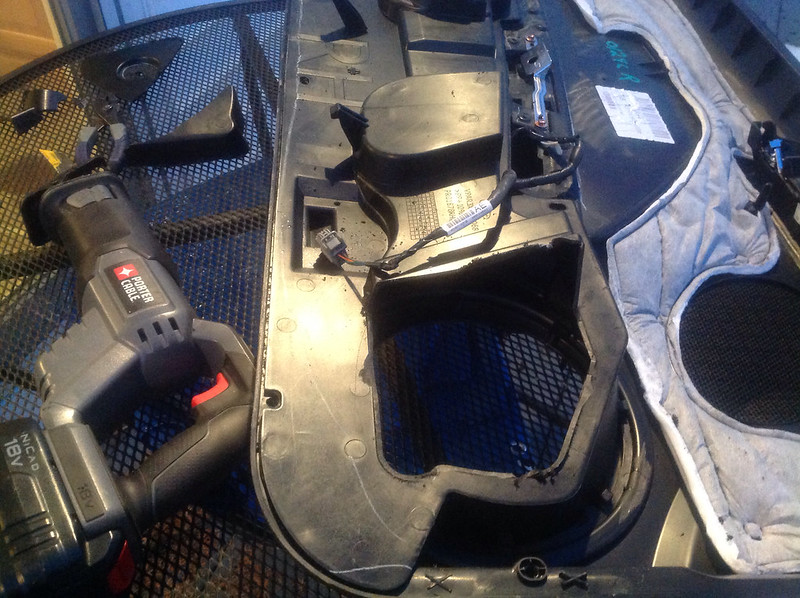
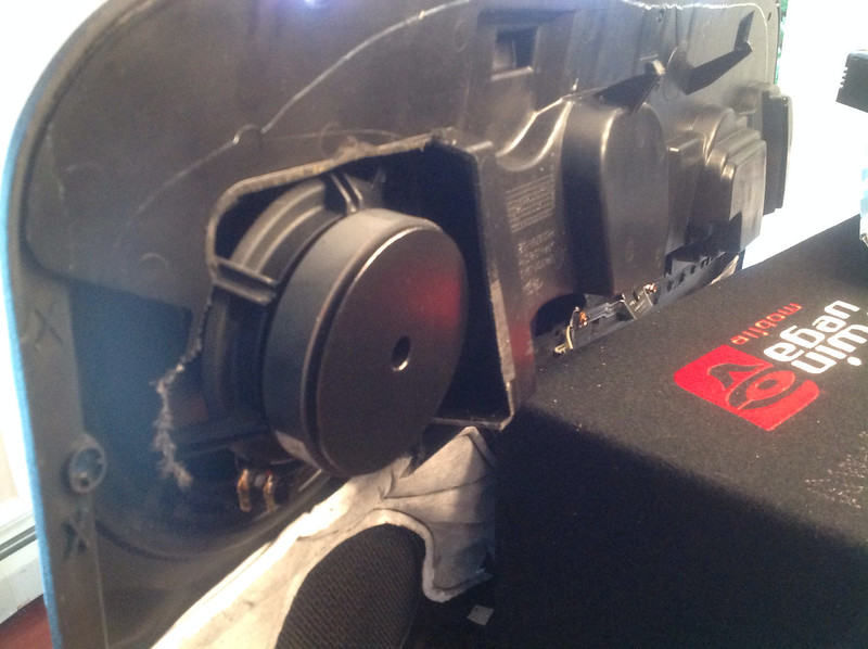
So the first order of business is to remove the stock door panels, remove the JL Audio coxials, and re-purpose the OEM speaker bracket to house the 6.5" Infinity driver. The problem using the bracket is that now there is open air space on either side. The solution was cut out material from a heavy duty storage tote. I had tried a small tote, but the plastic was brittle, but the bigger green tote lid was just right. Once I'm ready for final install, I will seal up the bracket surface & tote material with silicone adhesive.


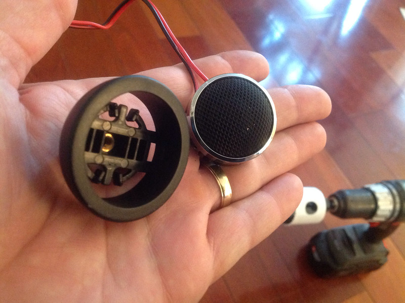
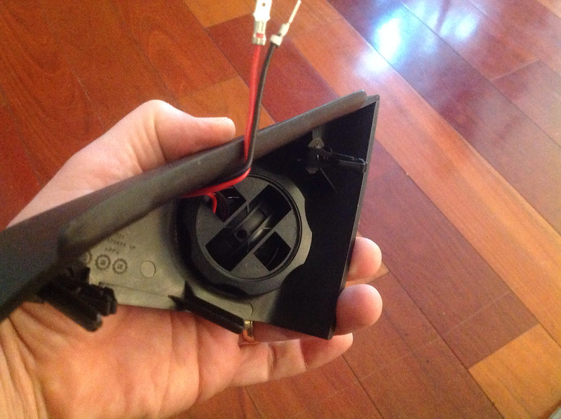
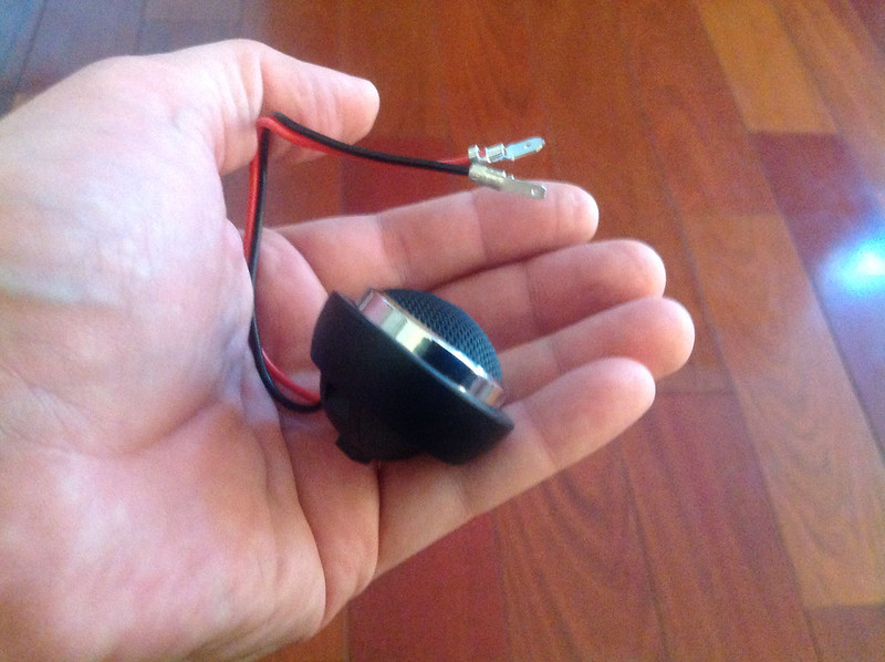
As this post is already long, the component tweeter & Dayton woofer install will follow.
Once you know you need to replace the head unit, finding a replacement dash panel is required. I really wasn't too impressed with the appearance of the Metra & Scoche kits, and was glad to see the iDatalink Maestro kit hit the market. I was critical of the initial cost when this was released, but I got lucky and snagged the ADS-KIT-MUS1 and RR module for 249$ new/shipped from eBay. I couldn't be happier with the quality, fit and finish. Props the manufacturer, iDatalink really impresses with their product line, engineering, web site, and attention to detail. The fact that we have 12v Guy here to answer questions and offer help and advice is a much appreciated bonus.
Since I had tried the incremental upgrade approach - replace all speakers - suck - add PAC Audio interface to feed amplifier - more suck, fail - it was time to go whole hog. So the time came to put together a list of components and materials. Since I had already installed an old, scratch that, *ancient* Yamaha 4ch amp to power the JL Audio coaxials, I already have the amp install kit installed. Now it's one inline fuse and wires run through the firewall from the pre-cut hole in the firewall thanks to the sound tube delete kit grommet. My arm is sore from patting myself on the back for running TWO power wires, as I knew I would be adding a second amp. I figured I could address the need for a 2nd fuse later (now if recommended), but at least that part is done.
Another reason my shoulder is sore, is that I came up with an innovative way to temporarily mount the amplifier in the trunk. I got some industrial strength tie wraps, and looped them around the rear deck and seat area. From those I was able to suspend the amp by running another set of tie wraps through the 4 corner mount holes of the amp through the loops created by the 1st set of tie wraps around the body panels. The beauty of this setup is that you can adjust the tension of the wraps as needed. A piece of foam can be wedged between the rear deck to prevent the amp from bouncing upward in event of a hard bump. This setup is also quite handy as you can snip the secondary set of ties to 'uninstall' the amp so you can make adjustments as needed, and then re-tie. I may copy the plywood and angle bracket setup shown in clucas build thread for my amps.
On a side note, using this old amp wasn't such a hot idea. After a few weeks use, one of the channels started to fail. As a side effect, Sync voice prompts ceased to function, even after yanking the battery cable and performing a factory reset. Once the faulty amp was removed, Sync functions returned.
The equipment list (links provided for reference only, all gear purchased through Amazon, Parts-Express, or Ebay);
Kenwood DNX690HD
http://www.kenwoodusa.com/Car_Entertainment/eXcelon/Mobile_Video_n_Navigation/DNX690HD
iDatalink ADS-KIT-MUS1 & RR Module
http://maestro.idatalink.com/search...013&vehicle_model_id=66&vehicle_audio_id=8478
Crunch Audio DRA 1450.4 4x175w
http://www.sonicelectronix.com/pictures_new.php?id=67958&picture_id=1300073
Infinity Kappa 6.5 60.11cs
http://www.sonicelectronix.com/pictures_new.php?id=60700&picture_id=-1
Dayton Audio RS-255-8
http://www.parts-express.com/dayton-audio-rs225-8-8-reference-woofer--295-356
Cerwin Vega HEDBK212
http://www.sonicelectronix.com/item_39705_Cerwin-Vega-HEDBK212.html
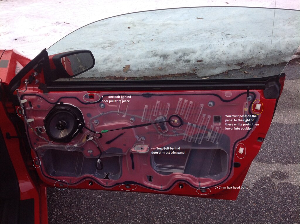
When I bought my Boss, I knew I would be upgrading the audio, so I purchased a pair of GT Premium door panels, complete with all hardware and switches.
As I was having a hard time finding some JL ZR-800s for a decent price, I picked up a pair of Dayton Audio RS-255s. Great reviews and feedback on these, and I'm very happy with the pair of 10" Dayton Audio powered subwoofers, so I'm liking the brand so far.
No comparison to the wimpy & cheap stock speaker.
So the first order of business is to remove the stock door panels, remove the JL Audio coxials, and re-purpose the OEM speaker bracket to house the 6.5" Infinity driver. The problem using the bracket is that now there is open air space on either side. The solution was cut out material from a heavy duty storage tote. I had tried a small tote, but the plastic was brittle, but the bigger green tote lid was just right. Once I'm ready for final install, I will seal up the bracket surface & tote material with silicone adhesive.
As this post is already long, the component tweeter & Dayton woofer install will follow.