Tracking an 03

racebronco2

Well-Known Member
Established Member
Joined
Sep 23, 2003
Messages
7,268
Location
palmdale, ca
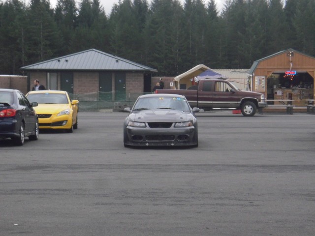
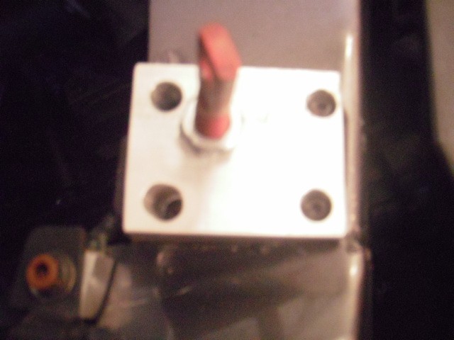
We are finally getting the Cobra back on the track been screwing with the kit car but finally pulled it off the rack. I never got the top of the radiator completely boxed. In the last couple of years it has become quite apparent the hood latch is a major headache on the track so I decided to pull it and replace with pins. I closed off the top of the radiator with some .050 aluminum sheet. We formed an L shape and bolted it on using the existing latch hardware. The L shape is riveted to the block off plate. The block off plate seals above the radiator fins. No more leaking out the top.

View attachment 71918

I was reading some old posts about the cars getting light with fully boxed systems. I believe Carlos left one of the panels out for high speed runs to vent pressure. I was wondering if any one had used block off plates for the inlets. Using Bernoulli we could calculate the 2 areas (radiator vs inlet) and then restrict the inlet area (drill holes in the blocking panels) to control the pressure at the face of the radiator.

I remove the bottom panel for high speed runs. There is not enough air flow thru the radiator over 140mph. Not sure what the optimum speed for a boxed in system.
 

iismet

Member
Established Member
Joined
Feb 26, 2004
Messages
206
Location
Portland Oregon
Promising

fD6E1w.jpg

eSC8IY.jpg

Relocate support rod
3R4pyv.jpg

XvriEh.jpg
 

iismet

Member
Established Member
Joined
Feb 26, 2004
Messages
206
Location
Portland Oregon
I remove the bottom panel for high speed runs. There is not enough air flow thru the radiator over 140mph. Not sure what the optimum speed for a boxed in system.

I was looking at => a1 v1 p1 = a2 v2 p2

and by reducing the inlet area we could increase the velocity while maintaining the pressure. I have no idea what the pressure is, but my car stays cool while running up to 135.

=> solving for a2 => a1 v1 p1 /v2 p2

Since we want the pressure to remain constant p1 and p2 cancel each other out leaving

a2 = a1 v1 / v2

So

v1 = 135
a1 = factory inlet area
v2 = 160 (170, 180 etc)

I was thinking of fabricating contoured blocking panels which could be drilled to provide the appropriate a2. Take it to the track and run the crap out of it paying attention to h20 temp. Tape and or drill as needed. Pegasus sells different density wire mesh that may work. This would move the air around and over as opposed to the bottom.

I am not this far along. Top speed on the 3 tracks we run is around 135. It may be possible to get more at The Ridge, but I don't have enough experience there to know how much speed I can carry into turn 1. Should I run into lifting issues this is a path I plan to pursue.
 

iismet

Member
Established Member
Joined
Feb 26, 2004
Messages
206
Location
Portland Oregon
Hood Pins Finished

Vb3H6J.jpg

We leveled the splitter and increased the dam height 1/2" a 4x4 will not pass under

gthTSv.jpg

zMz4sP.jpg

Pulled the cats and tucked the exhaust up

vKonvL.jpg

cYyk46.jpg
 

iismet

Member
Established Member
Joined
Feb 26, 2004
Messages
206
Location
Portland Oregon
We got to run the last HOD day at the ridge last weekend. It had been raining for several days prior and was wet when we got there. The rain held off until the last session which I got to run. I love running in the rain, but was a little nervous running on the R7's.

We ran the Continentals in the morning

6GnKN1.jpg

Cool damp air all day - the car ran great

wj7Akn.jpg

It dried out and we put the R7's on for the afternoon

qHgxDg.jpg

Our Hauler

3zPs2D.jpg

2sTjTC.jpg

Back to cooling the trans

chr
 
Last edited:

racebronco2

Well-Known Member
Established Member
Joined
Sep 23, 2003
Messages
7,268
Location
palmdale, ca
I for one thanks you for the progress you made. Most people do not have the time or resources to get the things done that you have done.
 

iismet

Member
Established Member
Joined
Feb 26, 2004
Messages
206
Location
Portland Oregon
I think the thanks should go to you and all the guys who put effort into these cars over the years that were willing to share tech. A lot of trees were chopped down for others like me.

At one point I almost sold it - I am so thankful I did not. Studying, building, and tracking is something I really enjoy and I am quite fortunate to be in a position to do so. It brings a smile every time we start it.

Your work has always been inspiring. I still reference your stuff all the time - wish the pictures were still around :-D

x-chr
 

iismet

Member
Established Member
Joined
Feb 26, 2004
Messages
206
Location
Portland Oregon
I've been meaning to post up some dimensions for the Aerocatch pin block. I got a recent request from a member so here it is.

The as-built drawing below shows both pin holes for ease of making the drawing. You only need one per block and the pins go to the inside. The pins are metric I believe and I don't remember what size they are so you will want to purchase your catches and and determine the thread size.

2DvOWO.jpg


Note 1 - The "thread thru (2) places" would only be used if the fabricator elected to put both pin holes in a block which is not needed.

Note 2 - The angle above comes out to 16 degrees. We originally measured 15 but the whole thing was done on a napkin and a Bridgeport and I measured it yesterday with a tape and the car sitting in the trailer so pretty close - LOL! Fabricate to 15 deg is my recommendation.

Note 3 - We are running a True Fiber hood I can only guess this angle is correct for another hood. It will depend on the profile, but the fenders should be controlling the profile in this region. You can check this and correct if needed before you install your latch. At worst you can go back and as-built a new block to your latch if needed. The main thing is, with your pin acting as datum, your latches are located rotationally symmetrical on your hood. That is on you - see => Aerocatch install instructions.

O3cKNL.jpg


Note 4 - Our latches are located with respect to the factory threaded rubber stops and we used those witness marks to originally locate our holes. It was only after we were done that we realized the pin would not engage because of the difference in the angles. We used the same hole and as-built the blocks to those holes. This is of no concern - build your blocks and mount them next to the pinch weld you should be great. Carlos had documented this problem, but I was unaware of it until after.

So using the Aerocatch instructions and these blocks

1) Locate your blocks first - you will need to remove the OEM threaded stops.

2) Thread pin in and using a paint pen, Grease, etc etc. Coat the top of the pin and then lower the hood on to the pins such that there is a witness mark left on your hood.

3) Drill appropriate size hole thru the hood such that the pin will go thru.

4) Use something and run a sanity check on the angle it should be close to 90 degrees with respect to the latch. If it is not, determine an angle and cut a new block. I have a feeling the drawing will work because the fenders should be controlling the profile of the hood.

5) Locate your latch to your pin using the supplied Aerocatch template.

6) My hood is CF so we used a cutoff wheel to cut the latch hole - YMMV

7) Attach your latch

8) Adjust the vertical pin height such that the latch catch pin easily engages the vertical pin and the hood height is correct


nCiqDe.jpg


1) The block is located off of the pinch welds.

2) We used 10x24 riv-nuts and button head screws to attach to the the sheet metal.

3) We drilled a clearance hole below the pin so it would not bottom out. This may not be needed but we were lazy in figuring it all out.

4) Notice the strange pin rotation. Your latch will dictate this

5) Notice there is only one pin hole (differs from drawing)

This is a really nice mod if you are tracking your car.

Lastly - If you totally f3k it up, please remember - I am just some guy on the web, but If I can do it - anybody can - LOL!!

chr
 

Attachments

  • wedge 11-30-2016.jpg
    wedge 11-30-2016.jpg
    89.7 KB · Views: 349
  • P6300653.JPG
    P6300653.JPG
    81.5 KB · Views: 334
Last edited:

iismet

Member
Established Member
Joined
Feb 26, 2004
Messages
206
Location
Portland Oregon
We have big plans for 2018. Our goals for 2018

1) Rebuild the IRS with a Full Tilt kit
2) Re-gear to 3:73
3) Construct a full flat bottom
4) Construct a rear diffuser
5) Put the car back on X2s which will leave us at 2.5 above ground

We have been at it a couple of weeks now. Originally I was going to route the exhaust down the tunnel and blow the diffuser with the exhaust. I abandoned this because of the heat concerns. That said, the stock Cobra routing around the IRS would be a no brainer.

Abandoning blowing the diffuser, we started working on side exhaust. We fabbed new rockers which puts the floor 3" above the ground. This completely encloses the MM SFCs. We had to push the rocker out about 1/8" to make the cavity big enough to get the exhaust and a burns muffler into. We will insulate the body side.

A Pic of our first mock up. It includes a turning vane at the front to try to vent tire wake outside.

EP3L5L.jpg


We plan to run the exhaust behind the turning vane . The exhaust will exit thru the rocker not the body.
Nfnkl2.jpg


The diffuser will have an 8 degree ceiling and vertical fences with their bottoms in the same plane as the floor.

Will get some more pics up shortly.

chr
 
Last edited:

03 DSG Snake

Unknown Cyborg
Established Member
Joined
Nov 3, 2002
Messages
21,049
Location
CA
We have big plans for 2018. Our goals for 2018

1) Rebuild the IRS with a Full Tilt kit
2) Re-gear to 3:73
3) Construct a full flat bottom
4) Construct a rear diffuser
5) Put the car back on X2s which will leave us at 2.5 above ground

We have been at it a couple of weeks now. Originally I was going to route the exhaust down the tunnel and blow the diffuser with the exhaust. I abandoned this because of the heat concerns. That said, the stock Cobra routing around the IRS would be a no brainer.

Abandoning blowing the diffuser, we started working on side exhaust. We fabbed new rockers which puts the floor 3" above the ground. This completely encloses the MM SFCs. We had to push the rocker out about 1/8" to make the cavity big enough to get the exhaust and a burns muffler into. We will insulate the body side.

A Pic of our first mock up. It includes a turning vane at the front to try to vent tire wake outside.

View attachment 1484175

We plan to run the exhaust behind the turning vane . The exhaust will exit thru the rocker not the body.
View attachment 1484176

The diffuser will have an 8 degree ceiling and vertical fences with their bottoms in the same plane as the floor.

Will get some more pics up shortly.

chr

This car has been very exciting to follow so far. Looking forward to more.
 

iismet

Member
Established Member
Joined
Feb 26, 2004
Messages
206
Location
Portland Oregon
Here is our latest rev with the outlet properly placed.

TVa0yl.jpg


This is an L shape we are using to box the exhaust tunnel. It is riveted to the pinch weld. The horizontal surface gets riv-nuts which the floor will attach to. The floor closes the tunnel. The door sill down to the horizontal get DEI insulate.
3pPcES.jpg


You can just see the wrapped exhaust in the back ground. A new one will route thru this cut and turn into the tunnel. The angle of the turn will be less than 90.
EBDg69.jpg


Another of the turning vane. You can see the wrapped pipe in the background. It will be routed behind the vane. I plan to do some testing on the vane if it does not do as we hope, we will go back to the stock trim piece or fabricate a new fill piece.

Notice the door trim on the bottom of the door. We are using this to seal the bottom of the door to the top of the rocker.
WDFHF3.jpg


Can any of you recommend how to hang the exhaust in the tunnel?
chr
 

iismet

Member
Established Member
Joined
Feb 26, 2004
Messages
206
Location
Portland Oregon
This pic shows how far we have dropped the floor. We have run partial sheeting for several years unfortunately it was not flat, except at the outboard section. The inner section followed the SFCs which made it rather swarfed (still helped us get over turn 9 at Portland :))

The bottom of the bracket in the pic, was the top of the old floor which was attached to the bottom of the stock rockers. The new floor shown is 1.25 inches below the stock rockers.

With 275x35x17 and .250 chassis rake the new floor is 3.25 inches above the ground at the rear.

If we have enough tire clearance with X2s back in the car, we should be 2.5 front 2.75 at rear and I expect to get ground effect. I hope to be able to set the throat of the diffuser on the rear axle line. The diff is out being rebuilt with a Torsen. I am very anxious to get the IRS back in the car so we can layout the diffuser.
lPatkp.jpg


Edit : "With 275x35x17, MM K Member Bottom Holes, and .250 chassis rake the new floor is 3.25 inches above the ground at the rear.
 
Last edited:

iismet

Member
Established Member
Joined
Feb 26, 2004
Messages
206
Location
Portland Oregon
DEI insulation. Will wrap all the way under door and attach to door sill.
MpGJt5.jpg


2.5 dia
30Gtis.jpg


Burns 17 x 2.5 x 3.5. I have no idea if this will be enough. We are going to see about making it easily removable. If we can, we will run a straight pipe on a couple of tracks with no restrictions.
kCXTsO.jpg


A couple of SVO oval tips are on the way.
ZXBfqK.jpg


chr
 

iismet

Member
Established Member
Joined
Feb 26, 2004
Messages
206
Location
Portland Oregon
Some progress

q5Fvai.jpg


We've looked at a lot of options and have decided to hard mount to the door sill. The engine is hard mounted so we are going to weld in a flex coupler at the head of the side pipe. Our thinking is we'll break it or we won't.
51ojCD.jpg


We are fabbing brackets out of 16 gauge (.062) steel that will attach to the sill. The vertical straps bolt to the brackets. We will gusset the brackets and tack weld the nuts to the back side for ease of maintenance. The mufflers have to be periodically re-packed.
842PH6.jpg


We moved the assembly outboard providing .250 clearance at the tangency point of the muffler and the lower sill wall. This requires new rockers and outboard floor. The new rocker wall will need to be pushed outboard 1.250. The floor will need to be widened accordingly.
tgk22z.jpg


chr
 

iismet

Member
Established Member
Joined
Feb 26, 2004
Messages
206
Location
Portland Oregon
MhDLnP.jpg


Wat4jA.jpg


With the pipe hung with proper clearance we had to modify the rocker panel and push it further outboard. We are bending the new panel and will need a new floor panel to accommodate. We positioned the rear tire and reset the ride height and the bottom of the floor is within 1/8" of where it needs to be so the X2s may still be in play. We have dropped the floor 1 1/4 inches without changing the ride height. The floor is 2 7/8 above the ground surface.
VG2sTh.jpg
 

iismet

Member
Established Member
Joined
Feb 26, 2004
Messages
206
Location
Portland Oregon
We are on our 3rd major revision. I did some study on the Viper and found out several were burned to the ground because of fire in side the sill surround. We modified the cover so that we could attach it with dzus and we could remove it without having to open the door. This necessitated another cover and additional brackets under the extended sill which set us back some.

rO0lQz.jpg


Extended sill plate

f3zMpf.jpg


The cover attaches to the extended sill plate and the angle which is riveted to the floor.
irKIXQ.jpg


4aEQtP.jpg

This is a "T" shape riveted to the floor and attached at the forward fender bolt. This provided much needed rigidity to the forward part of the floor. The floor will get dzus to the engine cover. The exhaust passes to the right of the T shape.

nqNlJo.jpg


Mock up of the new cover with floor. The sub-frame connectors are completely covered.

BrYmeC.jpg
 

Users who are viewing this thread


Top