Hello everyone,
It's been a long time since I posted, as my build went on hold (2008), and my car was stored due to getting married, purchasing a home, and starting a Family. I have now been continuing the build (99 Cobra), and have a quick question regarding installing the power harness that comes from the battery terminals, and includes wiring to the starter, brackets for mounting organization, harness for oil pressure (near oil cooler), other harnesses that are located near battery tray (which I labeled initially and plugged in), and ground terminals. I have had most everything else labeled as well as the Ford Service manual, but volume 1, which does not contain this specific electrical install.
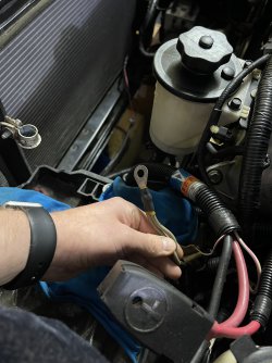
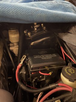
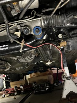
I have most everything in place, the three brackets mounted (two on the lower front engine cover, one on the passenger side engine mount bolt leading to the starter, and one larger that is mounted to the bracket that holds the power steering reservoir). The question is, there is a ground terminal that has two white wires leading to the circular ground end. Since most of the harness is in place, this wire ends up near the fuse box on the drivers side by the windshield washer fill location.
I have searched many avenues and have not found any luck, with partially close answers that are from threads 8-10 years ago. But, no clear answer.
If anyone can chime in, it would be greatly appreciated. Whether it is where to find the diagram, or have on hand knowledge.
Thanks in advance, and if there are any questions for more clarity, let me know.
-Ronald
It's been a long time since I posted, as my build went on hold (2008), and my car was stored due to getting married, purchasing a home, and starting a Family. I have now been continuing the build (99 Cobra), and have a quick question regarding installing the power harness that comes from the battery terminals, and includes wiring to the starter, brackets for mounting organization, harness for oil pressure (near oil cooler), other harnesses that are located near battery tray (which I labeled initially and plugged in), and ground terminals. I have had most everything else labeled as well as the Ford Service manual, but volume 1, which does not contain this specific electrical install.
I have most everything in place, the three brackets mounted (two on the lower front engine cover, one on the passenger side engine mount bolt leading to the starter, and one larger that is mounted to the bracket that holds the power steering reservoir). The question is, there is a ground terminal that has two white wires leading to the circular ground end. Since most of the harness is in place, this wire ends up near the fuse box on the drivers side by the windshield washer fill location.
I have searched many avenues and have not found any luck, with partially close answers that are from threads 8-10 years ago. But, no clear answer.
If anyone can chime in, it would be greatly appreciated. Whether it is where to find the diagram, or have on hand knowledge.
Thanks in advance, and if there are any questions for more clarity, let me know.
-Ronald