Very cool project! More importantly, you must have a very supportive and loving wife. As soon as I saw what looks to be diningroom pics, I was like nope, my wife would be flipping out. hahahahaha
You are using an out of date browser. It may not display this or other websites correctly.
You should upgrade or use an alternative browser.
You should upgrade or use an alternative browser.
The most UNIQUE mod...... you maybe?
- Thread starter Willie
- Start date
.
Will this be T'd off the degas tank or part of the flow path ??
It would include the install of the correct original 2013/14 bypass hose to complete the oem looking install. The only issue I have currently is my KB heat shield sits very close to the 2013/14 pump inlet nipple and it will require me to mod that shield, which I have not done yet. All other parts are in place and functioning including the hyd. power steering work around. All that is required now is to mod my KB CAI heat shield, install the 2013/14 bypass hose and use the plug and play VMP jumper extension to feed the 12v from the original I/C location to the new timing cover pump location below my P/S reservoir. It is all in place and I have not decided how I am going to mod that shield for the hose attachment on the pump.
This was the "test fit" with the oem 2013/14 bypass hose attached to the 2013/14 pump and the oem P/S reservoir and P/S pressure hose installed.....
The 2013/14 I/C pump hides very nicely below the P/S reservoir but is also installed like oem so everything connects correctly and appears that Ford put it there. On a 2011/12 EPS car, this would be a much easier mod.
On a 2007-2010 hyd. P/S car, the first obstacle is the P/S pressure steel line that is routed directly through the center of the 2013/14 I/C pump bracket......
R
Last edited:
Tried my hand and hand laminating some of the textured plastic pieces with carbon fiber for a fraction of the cost of actual carbon pieces. Came out decent but it's a very time consuming process. Currently working on a few other carbon fiber projects as well. Just dont have the free time I need to work on them.
View attachment 1620121
View attachment 1620122
Sanded down with 120 grit paper
View attachment 1620130
Initial wet layup, was a massive pain to get the fiber to stay stuck down in some places
View attachment 1620131
Epoxy resin layers finished ready for clean up
View attachment 1620132
All edges cleaned up and resin surface sanded with 120, 400, and finished with 800 grit paper
View attachment 1620133
Clear coat laid down. Looked nice and glossy but left an orange peel texture
View attachment 1620134
Wet sanded with 2000 and 3000 grit paper and ready for polishing.
View attachment 1620136
Finished result, still have to put it on the car though.
Sent from my SM-G960U using the svtperformance.com mobile app
Does that layup like fiberglass?
And I thought my remote trunk pop button was cool...
This is on my 04. I picked up an A pillar that had the SOS pods on it. It was a little beat up so I thought I'd try something. I also picked up a radio that was hands free capable, but I didn't want the mic just hanging from my visor. So I mounted the mic into the A pillar and then covered it in alcantara. I like how it turned out.


I installed the TC default "off" circuit over ten years ago. I know I drew it up back then, but finding it might not be so easy. However, it is a very simple circuit so I should be able to duplicate it without much effort. I can tell you now that you'll need one 12v SPDT relay and one Littlefuse Add-a-Circuit and wire of course. The theory behind it was this: The factory has one circuit that is hot only when the key is in the start position and that circuit's fuse is in the smart junction box. We tap into that circuit to supply a current to the relay when the key is in the start position. The relay energizes, closing a circuit that allows voltage to the TC circuit, just like when you push the button to turn it off. In essence, the relay turns the TC circuit off. Once you release the key from the start position, the relay opens (like letting off the button), the circuit is now Off and you're good to go.
I was intending on sharing a unique performance mod this time, but the above write-up was a little longer than I anticipated. I'm thinking I'll explain how I wired my trunk ice tank circuit, designed so I can switch to this system on the fly and believe it or not, I use a KB single out BAP..... So next time.....
Willie
I have several unique one of a kind custom design mods on my GT500.
I’ll start with my custom unique CAI which was designed and 3D printed back in 2014.
My first mod was the JLT 123mm CAI. The JLT 123mm is NOT real 123mm ID – it is 120mm ID (I measured that myself). After couple years then I tried the Steeda 130mm CAI but the Steeda tube is such a bad design. I have seen the C&L CAI in person and I can said the C&L CAI is the WORST. So, I decided to design my own custom CAI.
I first investigated different size of CAI available in the market. The stock OEM size is 105mm ID. The JLT 123 is actually 120mm ID. The FRPP CAI has 2 different size, 123mm and 148mm ID. The FRPP are true 123 and 148mm ID. The KB Gimme 5” is 5” OD – NOT ID. All tubing is sold in OD, not ID. The KB Gimme 5” is a 5” OD steel tubing with 18-gauge wall thickness (0.0478”). So, the ID is 127mm - 1.22mm - 1.22mm = 124.6mm.
The KB Gimme 5” can support 1000RWHP easily so I know 124mm ID is a good starting point. When selecting the ID size, I have to consider the idle speed quality and one of the factors is the idle airflow speed at the MAF sensor. At idle speed (750 RPM), the smaller ID (smaller cross section) would give better signal due to higher airflow speed but would limit the max HP at top end. The FRPP 148mm ID would give max HP but idle speed quality would not be as good as the 123 / 124mm ID (1mm ID would not make much different, a 10-degree change in inlet air temperature or IAT2 makes more different). Since idle quality is a main concern so I my final decision is 136mm ID.
Another factor is the air filter design. Most people don’t realize how much the air filter design can impact the engine performance. The JLT 123mm filter has 5” (127mm) opening with an integrated metal mesh design. There are 2 main purposes of the metal mash. First, it is the last line of defend in case some large foreign objects gone thru the filter elements. The other function is to straighten / smoothen (reduce turbulence) of the inlet air before reaching to the MAP sensor for better signal. But the downside is reduced opening and slows down inlet air speed. A typical metal mesh efficiency range from 0.21 to 0.24 depends on the wire diameter and the density of the mesh (in per in^2). The JLT 123mm intake filter has 5” opening with metal mesh (assume the mesh efficiency is 0.21) the total opening area is π*r^2 *0.79 = π*(63.5mm)^2 *0.79 = 10007.5mm2.
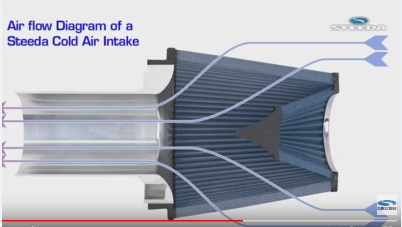
I started looking at different filter offer by several companies and 1 particular air filter caught my attention which is sold by Steeda. At that time I did NOT know there is a company PMAS CAI with a filter design exactly the same as Steeda except is a 7” (177.8mm) opening. This unique Steeda air filter design has 6” (152.4mm) opening without metal mesh. For those that do not know, the Steeda filter incorporates a reverse cone INSIDE the filter (shown in the below pictures) to straighten / smoothen (reduce turbulence) of the inlet air before reaching to the MAP sensor. The Steeda air filter has a 6” (152.4mm) opening without metal mesh so the total opening area is π*r^2 = π*(76.2mm)^2 = 18241.5mm2.


The last factor is the material used to make this CAI. For those that has the KB Gimme 5. You all know how hot that metal tube can get on a hot summer day with the hood closed. The intake air will pick up some of the heat from the heated KB metal intake tube which I don’t want. I need a material which has minimum thermal conductivity / heat transfer while can survival all the NVH issue inside the hot engine compartment. After talking to a co- worker and got a contact which leads to another contact, I finally got to the right person for the material. He told me a material ALL major automaker (US, Japanese, etc) used to 3D print their intake manifold design for prototype testing, both on engine dyno and on vehicle field test. In fact, that’s the material most of the race team use to 3D print their intake manifold for engine dyno test result. He even shown me a returned 3D print intake manifold which survive 100,000 miles on vehicle field test. I asked him what would it take (cost) to 3D print my custom CAI for my GT500. He told me “just send me the file and see what I can do”. About 5 days later he told me my CAI is ready to pickup and that’s how I got it made at no cost – I guess I got lucky this time. I did ask him regarding the crystal-clear transparent resin used on the display engine cover and the answer is those 3D print clear transparent resin is ONLY for display purpose. They would not survive the under-hood environment.
When designing the CAI:
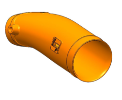
* It's a true 136mm ID CAI
* The outlet oval of the CAI has similar cross sectional area to the inlet elliptical cross sectional area of the KB throttle body
* A 1-piece design with extreme smooth transition in a span of at least 12” (304.8mm) in length. What I mean smooth transition is from true circle (136mm ID) right after the MAF sensor to the oval outlet (exit of the CAI). If you look at the KB Gimme 5 CAI. The 5” OD tubing is a straight tube then connects to 4” (101.6mm) in length silicon coupler. The coupler inlet is a 5” true circle and the outlet is an elliptical sharp which all happen in only 101.6mm in length. I want this transition happens in at least 12” long which gives much more smooth and gradual flow.
* The inlet has to have some kind of bell mouth feature to smooth out in coming air. (As mentioned earlier, I did not know PMAS sell the exact design air filter just like Steeda except in 7" opening. Otherwise I would choose the PMAS 7" opening filter so I can incorporate a much bigger and better smoother flow bell mouth inlet).
* It has the bungs for the 2 hose connections.
* Lastly, the design must have 2 positive stops – 1 for the air filter install and the other for the rear silicon coupler sits between the exit of the CAI and the throttle body inlet. For those has the JLT CAI, you all know there is not marking on the tube indicates how far the tube has inserted into the air filter nor the rear exit silicon coupler. You have to guess, then trial and error to find the right insertion length. JLT has no idea in term of design – they are quite LUCKY they sell lots of their CAI product. If I am the one design this JLT CAI and show it to the design chief / leader. I can guarantee he / she will kick my ass out of the door and I am not kidding. No body wants to guess and I would rather guess which stock would goes up in the near future or which numbers would show up in the next lottery drawing. That’s why I said JLT do NOT know anything in terms of design nor don’t know anything in terms of CAI design and don’t even know what a good air filter design.
Plan view:

Front view

Side view

True rear outlet view

3D printed in special engineering material (painted in school bus yellow) installed with KB 3.6L/C supercharger

I’ll start with my custom unique CAI which was designed and 3D printed back in 2014.
My first mod was the JLT 123mm CAI. The JLT 123mm is NOT real 123mm ID – it is 120mm ID (I measured that myself). After couple years then I tried the Steeda 130mm CAI but the Steeda tube is such a bad design. I have seen the C&L CAI in person and I can said the C&L CAI is the WORST. So, I decided to design my own custom CAI.
I first investigated different size of CAI available in the market. The stock OEM size is 105mm ID. The JLT 123 is actually 120mm ID. The FRPP CAI has 2 different size, 123mm and 148mm ID. The FRPP are true 123 and 148mm ID. The KB Gimme 5” is 5” OD – NOT ID. All tubing is sold in OD, not ID. The KB Gimme 5” is a 5” OD steel tubing with 18-gauge wall thickness (0.0478”). So, the ID is 127mm - 1.22mm - 1.22mm = 124.6mm.
The KB Gimme 5” can support 1000RWHP easily so I know 124mm ID is a good starting point. When selecting the ID size, I have to consider the idle speed quality and one of the factors is the idle airflow speed at the MAF sensor. At idle speed (750 RPM), the smaller ID (smaller cross section) would give better signal due to higher airflow speed but would limit the max HP at top end. The FRPP 148mm ID would give max HP but idle speed quality would not be as good as the 123 / 124mm ID (1mm ID would not make much different, a 10-degree change in inlet air temperature or IAT2 makes more different). Since idle quality is a main concern so I my final decision is 136mm ID.
Another factor is the air filter design. Most people don’t realize how much the air filter design can impact the engine performance. The JLT 123mm filter has 5” (127mm) opening with an integrated metal mesh design. There are 2 main purposes of the metal mash. First, it is the last line of defend in case some large foreign objects gone thru the filter elements. The other function is to straighten / smoothen (reduce turbulence) of the inlet air before reaching to the MAP sensor for better signal. But the downside is reduced opening and slows down inlet air speed. A typical metal mesh efficiency range from 0.21 to 0.24 depends on the wire diameter and the density of the mesh (in per in^2). The JLT 123mm intake filter has 5” opening with metal mesh (assume the mesh efficiency is 0.21) the total opening area is π*r^2 *0.79 = π*(63.5mm)^2 *0.79 = 10007.5mm2.
I started looking at different filter offer by several companies and 1 particular air filter caught my attention which is sold by Steeda. At that time I did NOT know there is a company PMAS CAI with a filter design exactly the same as Steeda except is a 7” (177.8mm) opening. This unique Steeda air filter design has 6” (152.4mm) opening without metal mesh. For those that do not know, the Steeda filter incorporates a reverse cone INSIDE the filter (shown in the below pictures) to straighten / smoothen (reduce turbulence) of the inlet air before reaching to the MAP sensor. The Steeda air filter has a 6” (152.4mm) opening without metal mesh so the total opening area is π*r^2 = π*(76.2mm)^2 = 18241.5mm2.
The last factor is the material used to make this CAI. For those that has the KB Gimme 5. You all know how hot that metal tube can get on a hot summer day with the hood closed. The intake air will pick up some of the heat from the heated KB metal intake tube which I don’t want. I need a material which has minimum thermal conductivity / heat transfer while can survival all the NVH issue inside the hot engine compartment. After talking to a co- worker and got a contact which leads to another contact, I finally got to the right person for the material. He told me a material ALL major automaker (US, Japanese, etc) used to 3D print their intake manifold design for prototype testing, both on engine dyno and on vehicle field test. In fact, that’s the material most of the race team use to 3D print their intake manifold for engine dyno test result. He even shown me a returned 3D print intake manifold which survive 100,000 miles on vehicle field test. I asked him what would it take (cost) to 3D print my custom CAI for my GT500. He told me “just send me the file and see what I can do”. About 5 days later he told me my CAI is ready to pickup and that’s how I got it made at no cost – I guess I got lucky this time. I did ask him regarding the crystal-clear transparent resin used on the display engine cover and the answer is those 3D print clear transparent resin is ONLY for display purpose. They would not survive the under-hood environment.
When designing the CAI:
* It's a true 136mm ID CAI
* The outlet oval of the CAI has similar cross sectional area to the inlet elliptical cross sectional area of the KB throttle body
* A 1-piece design with extreme smooth transition in a span of at least 12” (304.8mm) in length. What I mean smooth transition is from true circle (136mm ID) right after the MAF sensor to the oval outlet (exit of the CAI). If you look at the KB Gimme 5 CAI. The 5” OD tubing is a straight tube then connects to 4” (101.6mm) in length silicon coupler. The coupler inlet is a 5” true circle and the outlet is an elliptical sharp which all happen in only 101.6mm in length. I want this transition happens in at least 12” long which gives much more smooth and gradual flow.
* The inlet has to have some kind of bell mouth feature to smooth out in coming air. (As mentioned earlier, I did not know PMAS sell the exact design air filter just like Steeda except in 7" opening. Otherwise I would choose the PMAS 7" opening filter so I can incorporate a much bigger and better smoother flow bell mouth inlet).
* It has the bungs for the 2 hose connections.
* Lastly, the design must have 2 positive stops – 1 for the air filter install and the other for the rear silicon coupler sits between the exit of the CAI and the throttle body inlet. For those has the JLT CAI, you all know there is not marking on the tube indicates how far the tube has inserted into the air filter nor the rear exit silicon coupler. You have to guess, then trial and error to find the right insertion length. JLT has no idea in term of design – they are quite LUCKY they sell lots of their CAI product. If I am the one design this JLT CAI and show it to the design chief / leader. I can guarantee he / she will kick my ass out of the door and I am not kidding. No body wants to guess and I would rather guess which stock would goes up in the near future or which numbers would show up in the next lottery drawing. That’s why I said JLT do NOT know anything in terms of design nor don’t know anything in terms of CAI design and don’t even know what a good air filter design.
Plan view:
Front view
Side view
True rear outlet view
3D printed in special engineering material (painted in school bus yellow) installed with KB 3.6L/C supercharger
Attachments
That CAI is pretty cool. I'd love to do something like that. Especially now that I'm not running a MAF anymore.
I like your 3D printed tube, similar to my JDM tube but without the downward bend.
On your air filter, the cone will help direct air,..........that comes in from the end. It does little for the air that enters through the grille snorkel in your last pic..
.
On your air filter, the cone will help direct air,..........that comes in from the end. It does little for the air that enters through the grille snorkel in your last pic..
.
Double post..
Last edited:
Triple post ?????????
I like your 3D printed tube, similar to my JDM tube but without the downward bend.
On your air filter, the cone will help direct air,..........that comes in from the end. It does little for the air that enters through the grille snorkel in your last pic..
.
You are corrected. The snorkel portion would not do much but other area would still benefit from that. Every little bit that can help to smooth out the incoming inlet air is good.
I did thought about the JDM tube back in 2014 but one thing I don't like it is a 2- pieces design which requires 2 couplers. I want a 1 piece design with minimum connections.
Love my headlights. Prob what gets the most attention on the car.

more on these headlights please
more on these headlights please
Talking pics or details?
- Internals painted gloss black. Body shop not rattle can paint
- Morimoto H1 7.0 bi-xenon Projectors
- Flash back LED Strip (Goes amber when turn singal is active)
- RGB Demon Eyes
- Also Blacked out the turn signals with spray on tint.
I think I forgot half the shit I did for mine. Great thread.
^^^Yes, me too. Over 12 years of ownership can bring on many mods.
R
Users who are viewing this thread
Total: 2 (members: 0, guests: 2)

